
Line operated thyristor control time delay
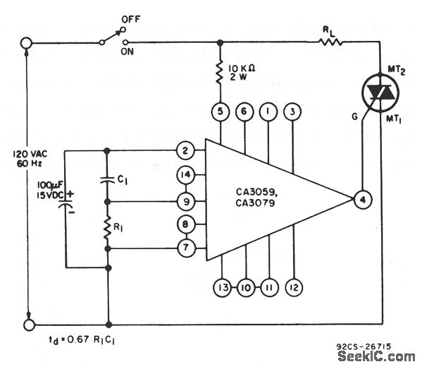
The circuit operates by taking advantage of the characteristics of the CA3059 or CA3079, which are designed to provide a controlled zero-voltage switching mechanism. This feature allows for precise timing control when activating a triac, which is commonly used for AC load control applications.
In the circuit, the resistor (R) and capacitor (C) form an RC timing network that dictates the delay period. When the switch is closed, the capacitor begins to charge through the resistor. The time constant of the RC network is defined as τ = R × C, where τ represents the time it takes for the capacitor to charge to approximately 63.2% of the supply voltage. The voltage across the capacitor will rise exponentially until it reaches the threshold voltage necessary to trigger the triac.
Once the triac is triggered, it will remain in the 'on' state as long as there is sufficient current flowing through it, allowing for the control of AC loads without the need for mechanical switching. The precise values of R and C can be adjusted to modify the delay time, allowing for customization based on the specific requirements of the application.
This circuit design is particularly advantageous in applications where soft-start mechanisms are desired, minimizing inrush currents and extending the lifespan of connected components. Additionally, the use of zero-voltage switching reduces electromagnetic interference (EMI), making it suitable for sensitive electronic environments.
Overall, the combination of the CA3059 or CA3079 with a tailored RC timing network provides an effective solution for controlling the turn-on timing of triacs in various electronic applications.This circuit uses a CA3059 or CA3079 zero-voltage switch to control turn-on time of a triac. The delay between switch closure and turn-on is set by the values of R and C, as shown by the equation. 🔗 External reference
Related Circuits
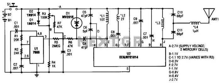
This transmitter can be utilized for multiple applications. An INS8048L microprocessor produces various codes based on keypad inputs. These codes are modulated onto a 40-kHz carrier frequency. Additionally, Q1 drives infrared LEDs LED1 and LED2. The transmitter circuit primarily consists...

The board can now be tested. Set the DIP switch to Switch1 ON, Switch2 OFF (15-second delay), Switch3 ON, and Switch4 OFF (4 rings to activate half for switching ON). To switch ON relay 1 (connected to RB0 of...

Efforts were made to minimize the number of wire jumpers on this board, but space constraints arose due to the integration of the microcontroller and motor driver on a single board. The design would have been cleaner without the...
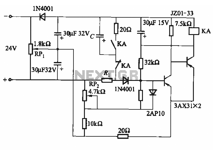
This circuit consists of five transistor time relay circuits designed for time relay exchange. It utilizes two different power supplies, maintaining the same circuit configuration. The delay time can be adjusted by modifying a potentiometer. The parameters for the...
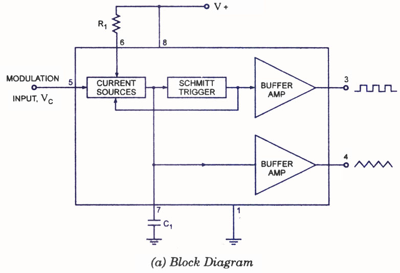
A voltage-controlled oscillator (VCO) is a type of oscillator in which the frequency of output oscillations can be adjusted by varying the amplitude of an input voltage signal. VCOs are commonly utilized in frequency modulation (FM), pulse modulation (PM),...
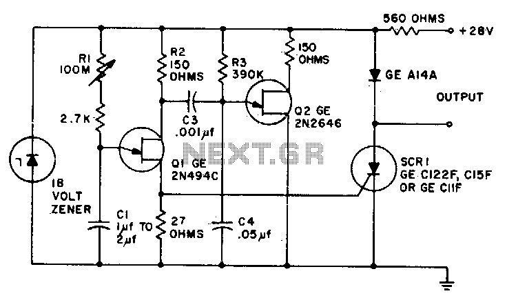
Predictable time delays ranging from 0 milliseconds to over 3 minutes can be achieved without the use of a large electrolytic timing capacitor. Instead, a stable low leakage paper or mylar capacitor is employed, effectively reducing the peak point...