
Speed Controler for R/C Models
An electronic speed controller (ESC) is a crucial component in remote control (RC) vehicles, allowing for the regulation of motor speed and direction. The design described utilizes an old servo mechanism in conjunction with MOSFETs to create a cost-effective ESC suitable for various applications, including RC cars, boats, and airplanes.
To construct the ESC, the first step involves selecting appropriate MOSFETs. The IRF530 and IRL2203N are recommended options. The IRF530 is a standard MOSFET that operates efficiently in various applications, while the IRL2203N is a logic-level MOSFET that can be driven directly by microcontrollers, making it advantageous for low-voltage control scenarios. When implementing multiple MOSFETs in parallel for increased current handling, it is essential to use the same type to ensure consistent switching characteristics and thermal performance.
The circuit typically begins with the servo's control signal, which is modified to drive the gate of the chosen MOSFET. The output from the servo is usually a pulse-width modulated (PWM) signal that varies in duty cycle to control the speed of the connected motor. The MOSFET acts as a switch, allowing current to flow through the motor when the gate is activated. The limited control range noted in the description indicates that the ESC operates more like a switch than a variable resistor, providing either full power or cut-off, which may be suitable for specific applications.
For assembly, the MOSFETs should be connected in a configuration where the source terminal is grounded, the drain terminal connects to the motor, and the gate terminal receives the PWM signal. It is advisable to include a flyback diode across the motor terminals to protect the MOSFET from voltage spikes generated when the motor is switched off. Additionally, proper heat sinking for the MOSFETs is recommended to prevent thermal overload during operation.
This simple ESC design is an effective way to repurpose old servos and create a functional speed controller for various RC applications, leveraging the characteristics of selected MOSFETs to achieve reliable performance.Here`s how you can make an electronic speed controler (ESC) for your remote control car, boat or even an airplane using an old servo and some MOSFETS. Please note that this ESC has a very limited control range. Meanining that it will act almost like but better then a switch. Choose from the following mosfets: IRF530 or IRL2203N. When using more than one mosfet, use the same type (either IRF530 or IRL2203). Based on Mosfet by Fairchild Semiconductors. (Varies with manufacturer) Note: IRL 2203N is a better mosfet for the u 🔗 External reference
Related Circuits
A Nidec TA450DC B35502-35 fan has been installed in a large wooden cabinet housing a computer and other electronics, which generates significant heat. The fan is designed to draw air from the room and exhaust it through openings at...
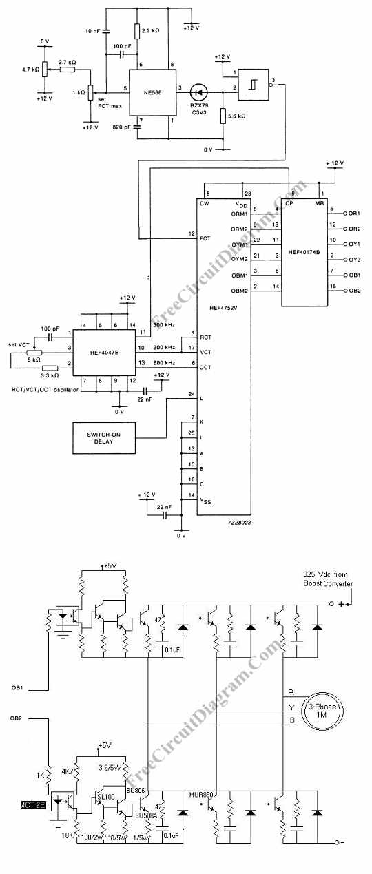
Controlling the speed of a three-phase AC motor is achieved by regulating the frequency of the power supply, as the motor operates in synchronization with the line. To control the speed of a three-phase AC motor, it is essential to...
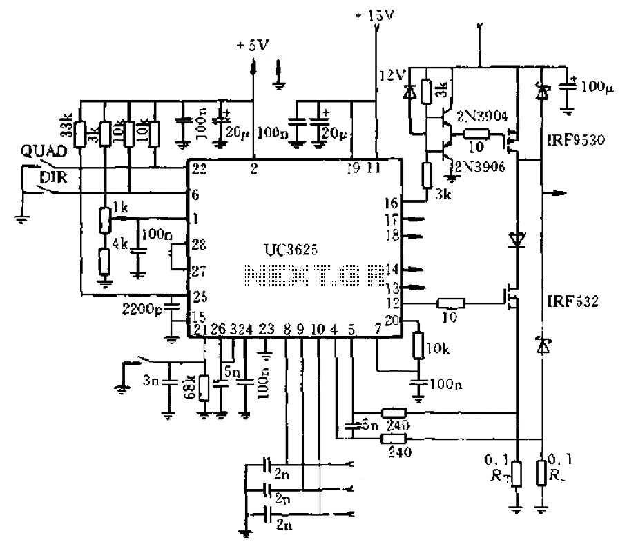
The circuit diagram represents a brushless DC motor driving circuit designed for a 45V/8A application. It features an open voltage-controlled design that allows for speed adjustment through an external potentiometer connected to a PWM duty cycle. The diagram illustrates...
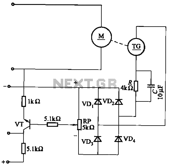
The capacitor C is part of the speed differential negative feedback system. The adjustment potentiometer RP allows for changing the amount of negative feedback. Both components can be utilized simultaneously within the circuit. The voltage (or speed) will only...
The proximity detector detects the movement of PC board pieces as the wheel rotates, generating an output signal with a clear transition between high and low voltage levels, making it suitable for triggering counting or processing circuits. Following this...
This circuit illustrates a Wiper Speed Control Circuit Diagram. The sweeping rate of the wiper can vary from once per second to once every ten seconds. The Wiper Speed Control Circuit is designed to regulate the speed of windshield wipers...
Warning: include(partials/cookie-banner.php): Failed to open stream: Permission denied in /var/www/html/nextgr/view-circuit.php on line 713
Warning: include(): Failed opening 'partials/cookie-banner.php' for inclusion (include_path='.:/usr/share/php') in /var/www/html/nextgr/view-circuit.php on line 713