
IR Remote Control Testers
The described circuit utilizes the SFH2030 photodiode, which is sensitive to infrared light, making it ideal for detecting signals from infrared remote controls. The CA3140 operational amplifier is chosen for its high input impedance and ability to operate in differential mode, which is crucial for accurately amplifying the small current generated by the photodiode when it receives infrared radiation.
In this configuration, the photodiode generates a current proportional to the intensity of the incoming infrared light. As the light intensity increases, the current through the photodiode also increases, leading to a corresponding increase in the output voltage from the operational amplifier. This output can be monitored using a multimeter set to measure DC voltage, providing a direct correlation between the infrared signal strength and the voltage reading.
LED1 serves as a visual indicator of infrared detection, illuminating when the photodiode is active. This feature not only provides immediate feedback but also aids in troubleshooting the circuit by confirming that the photodiode is receiving infrared signals.
The choice of power supply is flexible, with options for both 12 volts and 9 volts, allowing for versatility in different applications or setups. However, it is important to note that operational amplifiers such as the 741 or LF351 are not suitable due to their lower performance characteristics in this specific application, particularly in terms of bandwidth and input impedance.
This circuit can be effectively used for various applications, including remote control signal strength testing, infrared communication systems, and educational demonstrations on photodetection and signal amplification.A photodiode, SFH2030 as an infra red sensor. A MOSFET opamp, CA3140 is used in the differential mode to amplify the pulses of current from the photodiode. LED1 is an ordinary coloured led which will light when IR radiation is being received. The output of the opamp, pin 6 may be connected to a multimeter set to read DC volts. Infra red remote control strengths can be compared by the meter reading, the higher the reading, the stronger the infra red light. I aimed different remote control at the sensor from about 1 meter away when comparing results. For every microamp of current through the photodiode, about 1 volt is produced at the output. A 741 or LF351 will not work in this circuit. Although I have used a 12 volt power supply, a 9 volt battery will also work here. 🔗 External reference
Related Circuits
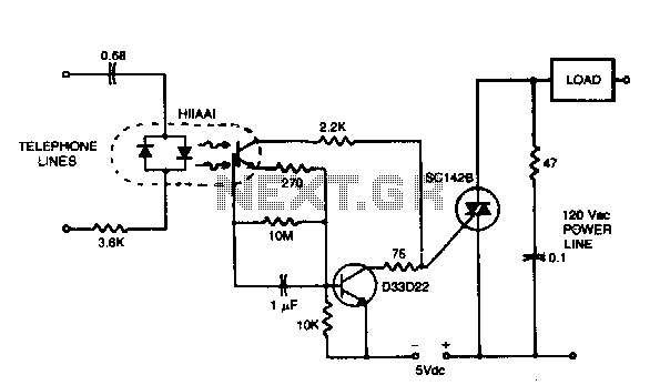
The circuit can operate lamps and buzzers from the 120 V, 60 Hz power line while maintaining positive isolation between the telephone line and the power line. The use of the isolated tab triac simplifies heat sinking by removing...
The following post illustrates a simple light-operated remote control circuit that can be activated by an ordinary flashlight or, more effectively, through a laser beam unit (keychain type). The Light Dependent Resistor (LDR) is connected between the base of...
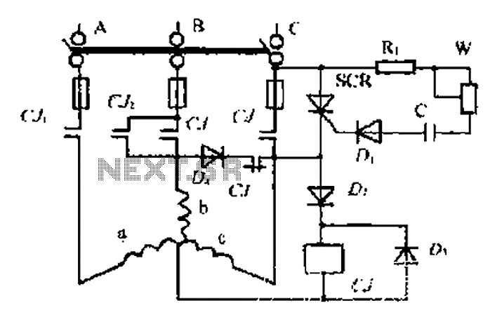
AC contactor controls suction units, with the motor activated simultaneously. A pair of contacts (CJ1) short-circuits the thyristor (SCR), turning it off. The contactor (C) is influenced by the diode's DC voltage. In the positive half-wave power cycle, the...
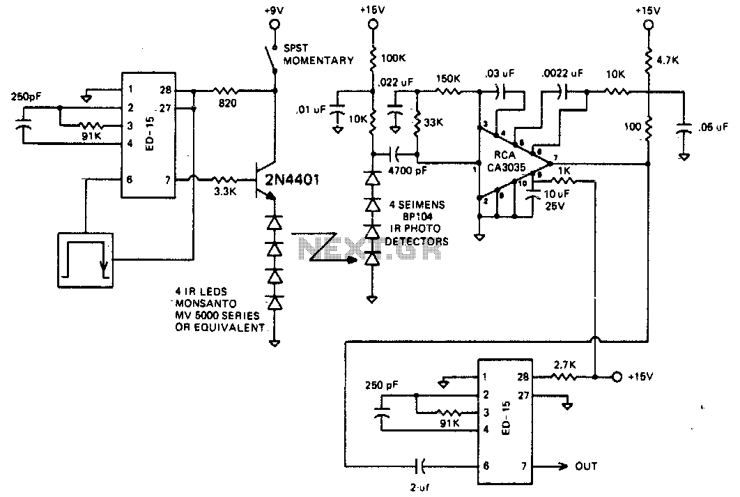
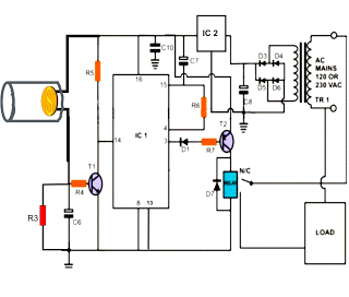
The circuit is designed to operate at 25 kHz. The data stream controls the 2N4401 transistor, turning it fully on or off based on the coded state. This action switches the series of infrared LEDs on and off. The...
This 555 timer based PWM controller features almost 0..100% pulse width regulation using R1, while keeping the oscillator frequency relatively stable. The frequency is dependent on values of R1 and C1, values shown will give a frequency range from...
The circuit allows for the remote control of electrical devices such as fans or lights using a standard TV remote. It operates effectively within a range of approximately 10 meters. The design features a 3-pin infrared (IR) receiver (Siemens...
Warning: include(partials/cookie-banner.php): Failed to open stream: Permission denied in /var/www/html/nextgr/view-circuit.php on line 713
Warning: include(): Failed opening 'partials/cookie-banner.php' for inclusion (include_path='.:/usr/share/php') in /var/www/html/nextgr/view-circuit.php on line 713