
An induction motor dynamic braking control circuit
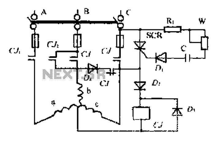
The circuit utilizes an AC contactor to manage the operation of suction units, integrating a thyristor (SCR) for effective control of the motor's operation. The contactor's primary function is to switch the motor on and off, ensuring that the suction units operate efficiently. When the motor is activated, the contacts CJ1 create a short circuit across the SCR, effectively turning it off to prevent unintended current flow.
During the positive half of the AC waveform, the SCR is triggered through a series of components, including resistors and diodes, which provide the necessary gate current for conduction. The motor receives power through its b and c-phase windings, with contact CJ2 supplying a half-rectified current that supports the motor's operation. The SCR also plays a vital role in delivering bi-directional wave current, which is essential for maintaining the suction units' functionality.
As the positive half-cycle concludes, the induced back EMF in the b and c-phase windings activates the normally closed contact D4, allowing for a freewheeling path that ensures continuity of operation until the next half-cycle. This design prevents abrupt changes in current, contributing to the stability of the system.
The SCR is re-triggered at the onset of the next positive half-cycle, maintaining the current flow through the windings without interruption. The circuit is designed to manage energy efficiently, with charge storage mechanisms in place that allow for dynamic braking when necessary. This braking system minimizes mechanical wear and enhances the longevity of the motor.
Overall, the design emphasizes reliable operation and energy efficiency, utilizing the principles of AC control and SCR technology to achieve effective motor management in the context of suction units. The circuit is structured to ensure safe operation, with considerations for both dynamic braking and the prevention of undesired SCR exclusion under normal operating conditions.AC contactor Cli suction units, motor was switched on at the same time, CJ1 pair of contacts to the thyristor SCR shorted SCR it off. Contactor C interesting by the diode DC vo ltage and suction units, make energy system moving like love. In the positive half-wave power, SCR control electrode through R, W. C, Dl get trigger current conduction through, motor b, c-phase winding through the SCR, CJ2 contacts is to give a half rectified current, C is also provided by SCR BI wave current to maintain suction units. When the end of the positive half-wave current, b. c-phase winding fork induced electric boat, the D4. cl normally closed contact freewheeling. Sentenced next positive half cycle. SCR is turned on again. b, c-phase winding half do not have to fork crossing the current, past through the next cycle, c charge storage charges, SCR trigger current of less than bottles instead guide ila, complete small dynamic braking.
CJ, the power is not released, the SCR again through the small possibility of exclusion.
Related Circuits
This circuit automatically controls the headlight of a motorcycle, turning it on and off independently of the light and ignition switches, as long as the battery is fully charged. The initial stage employs a 220-ohm resistor and ZD1 to...
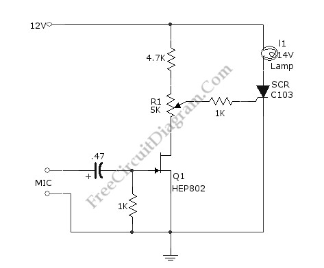
This simple circuit illustrated in the schematic diagram activates the switch using sound. It can be utilized for various applications, such as automatic (sound-controlled) disco lights or car LED light shows. The transistor Q1 amplifies the audio from the...
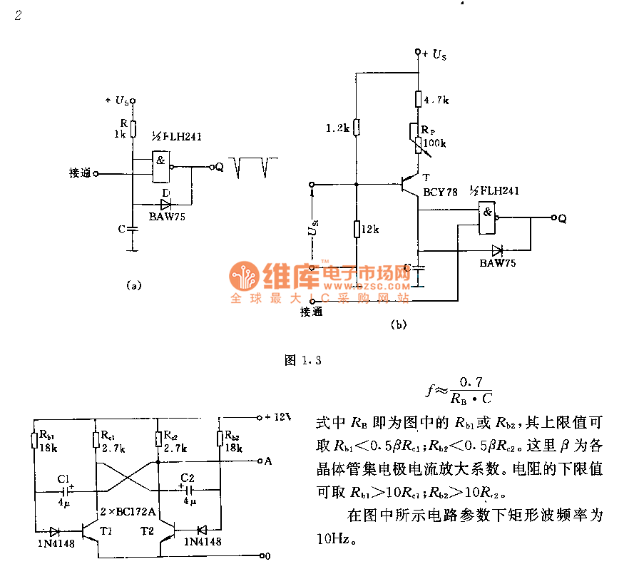
The circuit consists of two components whose parameters and models are designed to simultaneously generate a rectangular wave with a duty cycle of 1:1. The frequency is defined by the equation f = 0.7/(RB * C), where RB refers...

A high-power and efficient 100W power amplifier electronic project can be designed using the STK404 audio power amplifier hybrid ICs. These ICs consist of optimally designed discrete component power amplifier circuits that have been miniaturized using SANYO's unique insulated...
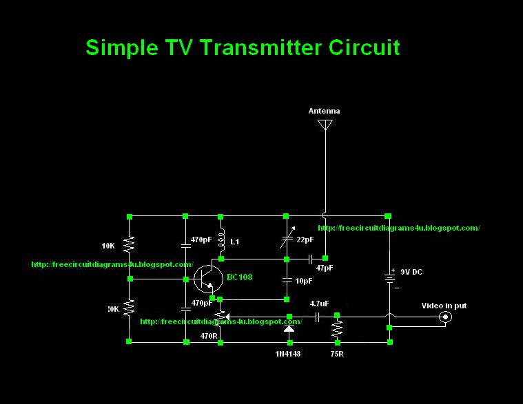
Many individuals inquire about TV transmitters. This document provides a useful circuit diagram that enables signal transmission over distances of 75 to 100 meters. The circuit diagram is not original; it was provided by a friend. Contributions of circuit...
The metal detector circuit consists of several key components including the probe oscillator, reference oscillator, oscillation signal processor, mixing amplifier, and ammeter PA. The probe oscillator is made up of the oscillating tube VI, exploration coil L1, capacitors C1...
Warning: include(partials/cookie-banner.php): Failed to open stream: Permission denied in /var/www/html/nextgr/view-circuit.php on line 713
Warning: include(): Failed opening 'partials/cookie-banner.php' for inclusion (include_path='.:/usr/share/php') in /var/www/html/nextgr/view-circuit.php on line 713