IR Remote Control Transmitter ATtiny28
Use of IR (infrared) light as a method for wireless communication has become popular for remote control applications. There are a number of different standards for such communication. In this application note, the widely used RC5 coding scheme from Philips will be described, and a fully working remote control solution will be presented. This application will use the ATtiny28 AVR microcontroller for this purpose. This powerful unit contains a hardware modulator, a high current LED driver, and interrupt options which makes it especially well suited for these kinds of applications. More: Utilizes ATtiny28 Special HW Modulator and High Current Drive Pin. Size Efficient Code, Leaves Room for Large User Code. Low Power Consumption through Intensive Use of Sleep Modes. Cost Effective through Few External Components. The RC5 code is a 14-bit word bi-phase coded signal. The two first bits are start bits, always having the value 1. The next bit is a control bit, which is toggled every time a button is pressed on the remote control transmitter. This gives an easy way of determining whether a button is pressed and held down, or pressed and released continuously. Five system bits hold the system address so that only the right system responds to the code. Usually, TV sets have the system address 0, VCRs the address 5 and so on. The command sequence is six bits long, allowing up to 64 different commands per address. The bits are transmitted in bi-phase code (also known as Manchester code). An example where the command 0x35 is sent to system 5 is shown. Note that the signal that enters the ATtiny28 hardware modulator is modulated with a certain carrier frequency. The ATtiny28 is a low-cost, high-performance 8-bit AVR RISC microcontroller with a number of features that makes it well suited for remote control applications. The built-in hardware modulator eases the task of generating the carrier frequency on which a data signal can be modulated. Frequency and duty-cycle are both easily changed by modifying the value residing in the Modulation Control Register MODCR. The high current driver on pin two of port A (PA2) is capable of driving a LED with a minimum of external components. This reduces size and system cost. In Power-down mode, the microcontroller can be configured to wake up on a low level from any pin on Port B. This provides an easy solution for waking up, scanning the keyboard, sending the command, and returning to Power-down mode. This application implements an easy keyboard scanning routine using Port B and Port D. Implementation shows the complete schematics for a remote control transmitter. The 455 kHz resonator gives the application a reliable and flexible clock base. The external LED driver circuit provides a constant current for the IR-LED. Resistor R3 determines the driver strength, and is in this application chosen to 7Ω giving a drive capability of approximately 100 mA. Higher resistor values will reduce current, and lowering the resistor value will increase driver strength. The diodes, D1 and D2, are present to ensure a close to constant driving current and to compensate for temperature variations in the transistor. In this application note, two different implementations will be presented; one low-cost solution requiring only a minimum of external components, and one using an external resonator and circuitry for driving the LED. The supplied code will work for both designs. For cost-sensitive applications with high tolerance on accuracy, a solution utilizing the internally calibrated RC Oscillator of the ATtiny28 could be used. The high current drive capabilities of PA2 can sink the LED directly, giving a solution with only a few external components. By using an external resonator and a driver circuit for the LED, a more flexible solution is achieved. The assembly code contains the latest RC5 Transmitter software. The main program flow can be divided into two routines. Both of them are interrupt-driven, and use different Power-down modes to reduce power consumption. The program is designed to use only one level of hardware stack, leaving two levels for user code. The main program loop starts with all registers being initiated; the hardware modulator is configured for correct frequency and duty-cycle. In this application, 38 kHz is used as the carrier frequency. This differs from the RC5 standard, which specifies 36 kHz for the carrier wave. The RC5 signal will, however, remain the same, and most standard RC5 Receivers should have no problem receiving and decoding the signal. Once the IO modules are initialized, the purpose of the main loop is to decide what sleep mode to use after the next wake-up. The main advantage is higher driver capabilities and higher frequency stability over the voltage range. If the receiver is self-synchronized, it will adapt to the changing frequency of the transmitter, and a solution using the internal RC Oscillator could be used with good results.
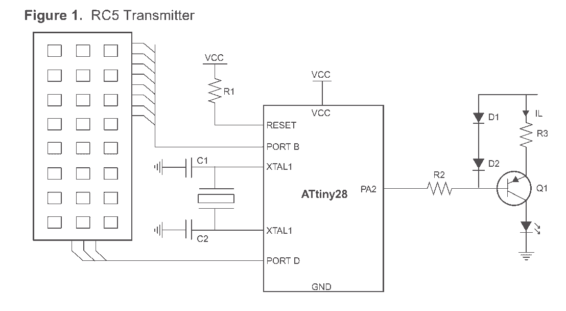
The described circuit employs an ATtiny28 microcontroller, which is integral to the implementation of an infrared (IR) remote control system utilizing the RC5 coding scheme. The circuit schematic includes several key components: an IR LED driven by a high-current output pin (PA2) of the ATtiny28, a 455 kHz resonator for clock generation, and a resistor (R3) to limit the current flowing through the LED, ensuring it operates within safe limits. The use of diodes (D1 and D2) enhances the stability of the current driving the LED, accounting for temperature variations that could affect the transistor's performance.
The RC5 protocol is utilized for encoding commands, with the microcontroller generating a bi-phase coded signal for transmission. The modulation frequency can be adjusted through the MODCR register, allowing flexibility in design. The circuit can be configured for low power consumption by leveraging sleep modes, ensuring that the remote control system can remain operational for extended periods without frequent battery replacements.
The implementation can be adapted to suit various applications, with the option of using either an internal RC oscillator for cost-sensitive designs or an external resonator for enhanced accuracy and performance. The software controlling the microcontroller is designed to handle interrupts efficiently, allowing for responsive command processing and user interaction through a simple keyboard scanning routine. This modular approach to circuit design allows for scalability and customization based on specific requirements, making it suitable for a range of remote control applications.Use of IR (infrared) light as a method for wireless communication has become popular for remote control applications. There are a number of different standards for such communication. In this application note the widely used RC5 coding scheme from Philips will be described, and a fully working remote control solution will be presented.
This application will use the ATtiny28 AVR microcontroller for this purpose. This powerful unit contains a hardware modulator, a high current LED driver and interrupt options which makes it especially well suited for these kinds of applications. Utilizes ATtiny28 Special HW Modulator and High Current Drive Pin Size Efficient Code, Leaves Room for Large User Code Low Power Consumption through Intensive Use of Sleep Modes Cost Effective through Few External Components The RC5 code is a 14-bit word bi-phase coded signal (see Figure 2). The two first bits are start bits, always having the value 1”. The next bit is a control bit, which is toggled every time a button is pressed on the remote control transmitter.
This gives an easy way of determining whether a button is pressed and held down, or pressed and released continuously. Five system bits hold the system address so that only the right system responds to the code. Usually, TV sets have the system address 0, VCRs the address 5 and so on. The command sequence is six bits long, allowing up to 64 different comm a n d s p e r a d d r e s s .
T h e b i t s a r e t r a n s m i t t e d i n b i - p h a s e c o d e ( a ls o k n ow n a s Manchester code) as shown in Figure 3. An example where the command 0x35 is sent to system 5 is shown in Figure 4. Note that Figure 3 and Figure 4 show the signal that enters the ATtiny28 hardware modulator. The actual signal emitted by the IR-LED will be modulated with a certain carrier frequency as shown in Figure 5.
ATtiny28: The Ideal Solution for Intelligent Remote Control Systems ATtiny28 is a low cost, high-performance 8-bit AVR RISC microcontroller with a number of features that makes it well suited for remote control applications. The built-in hardware modulator eases the task of generating the carrier frequency on which a data signal can be modulated.
Frequency and duty-cycle are both easily changed by modifying the value residing in the Modulation Control Register MODCR. The high current driver on pin two of port A (PA2) is capable of driving a LED with a minimum of external components.
This reduces size and system cost. In Power-down mode, the microcontroller can be configured to wake up on a low level from any pin on Port B. This provides an easy solution for waking up, scanning the keyboard, sending the command and returning to Power-down mode.
This application implements an easy keyboard scanning routine using Port B and Port D. Implementation Figure 1 shows the complete schematics for a remote control transmitter. The 455 kHz resonator gives the application a reliable and flexible clock base. The external LED driver circuit provides a constant current for the IR-LED. Resistor R3 determines the d river stre ng th, a nd is in this a pp l ica tio n cho se n to 7? giving a d rive cap ab i li ty o f approximately 100 mA. Higher resistor values will reduce current, and lowering the resistor value will increase driver strength.
The diodes, D1 and D2, are present to ensure a close to constant driving current and to compensate for temperature variations in the transistor. In this application note two different implementations will be presented; One low cost solution requiring only a minimum of external components, and one using an external resonator and circuitry for driving the LED.
The supplied code will work for both designs. Low Cost Implementation For cost sensitive applications with high tolerance on accuracy, a solution utilizing the internally calibrated RC Oscillator of the ATtiny28 could be used. The high current drive capabilities of PA2 can sink the LED directly giving a solution with only a few external components as shown in Figure 6.
By using an external resonator and a driver circuit for the LED, a more flexible solution is achieved. The assembly code found in the AVR415.ASM file contains the latest RC5 Transmitter software. The main program flow is shown in the flowchart in Figure 7. The program execution can be divided into two routines. Both of them are interrupt driven, and use different Powerdown modes to reduce power consumption. The program is designed to use only one level of hardware stack, leaving two levels for user code. Main The main program loop is shown in Figure 7. First all registers are initiated; The hardware modulator is configured for correct frequency and duty-cycle.
In this application 38 kHz is used as the carrier frequency. This differs from the RC5 standard, which specifies 36 kHz for the carrier wave. The RC5 signal will however be the same, and most standard RC5 Receivers should have no problem receiving and decoding the signal. Once the IO modules are initialized the purpose of the main loop is to decide what sleep mode to use after the next wake-up.
The main advantage is higher driver capabilities and higher frequency stability over voltage range. If however the receiver is self-synchronized, it will adapt to the changing frequency of the transmitter, and a solution using the internal RC Oscillator could be used with good results 🔗 External reference

