
Mini transistor Transmitter 50mW schematic
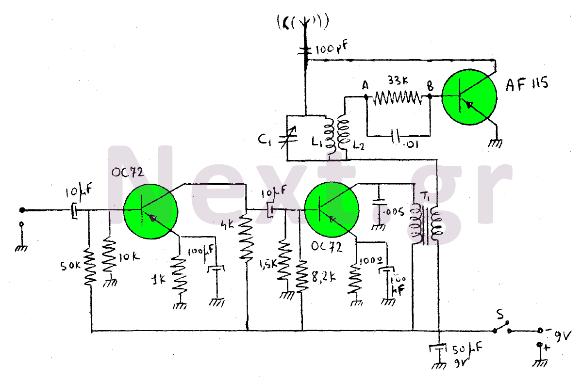
The L1 coil is composed of 60 turns of wire wrapped around a ferromagnetic core, with a diameter of 0.2 mm. The L2 coil consists of 10 turns, also wrapped around the same core above L1. If the oscillation does not function after assembly, the ends of coil L2 should be disconnected and reconnected in reverse. Capacitor C1 can be a small variable capacitor with a range of 300-500 pF, or it may be fixed at 500 pF. The antenna is designed to be foldable, measuring one meter in length. With precise construction, this transmitter can effectively transmit over a distance of 50 meters on medium waves. To modulate the oscillator carrier wave with music from an active source, the circuit involving the two OC72 transistors and transformer T1 is utilized.
This transmitter circuit is designed for medium-wave and short-wave operation, featuring a configuration that includes three key transistors. The AF115 acts as the oscillator, producing the necessary high-frequency signal. The OC72 transistors serve as a low-frequency amplifier, which modulates the oscillator's output to create a carrier wave. The integration of the small crystal microphone allows for sound input, enabling the transmission of audio signals.
The transformer T1 plays a critical role in the circuit as an adapter, with specifications indicating it is an AD9014 model. The construction of the coils is essential for the performance of the transmitter. The L1 coil, consisting of 60 turns of fine wire, is essential for establishing the inductance necessary for oscillation. The wire's diameter of 0.2 mm is chosen to balance resistance and inductive properties. The L2 coil, with its 10 turns, is positioned above L1 and can be adjusted for optimal performance. If the transmitter fails to oscillate, an adjustment of the coil connections may be required.
The capacitor C1 is a variable component that allows fine-tuning of the circuit, enhancing the transmitter's ability to operate effectively across the desired frequency range. The foldable antenna, measuring one meter, is designed for efficient transmission and can be easily deployed. With careful assembly and tuning, the transmitter can achieve a range of approximately 50 meters, making it suitable for various applications in medium-wave transmission. The circuit's design enables the incorporation of external audio sources, allowing for the modulation of the carrier wave, thus expanding the functionality of the transmitter beyond simple signal generation.Is this a transmitter? Medium-wave short-wave consists of three transistors. The transistor AF115, along with the rest of its circuitry, is the oscillator of the device. The circuit of the two OC72 is the low-frequency amplifier (modulator), which forms the carrier wave produced in the circuit of the AF115 lamp from its secondary transformer T1. The microphone is crystalline of small size. Transformer T1 is an adapter and has AD9014 data.
The L1 coil consists of 60 coils wrapped on a core of ferromagnetic material. The wire has a diameter of 0.2mm. Coil L2 consists of 10 coils wrapped on the same core above L1. When the construction is finished and the oscillation (load-generating device) does not work, then disconnect the ends of the coil L2 and connect them backwards.
Capacitor C1 is either a small variable of 300-500pF or even 500pF. The antenna of this transmitter is a foldable length of one meter With careful construction, this transmitter at mid waves reaches exactly 50 meters.
If we want to shape the oscillator carrier wave with music from an active source, then the circuit of the two OC72 (low frequency amplifier) including the T1 is over.
Related Circuits

The panels appear to be well-designed, and the cases are tidy. It is noted that the cases are constructed from MDF board. The panels are recessed significantly, likely to provide protection for the knobs. There is curiosity regarding the...

This USB circuit utilizes an integrated circuit (IC) to convert digital voice data into an analog format, making it suitable for headphone use. Additionally, the output can be amplified through a power amplifier, allowing the sound to be played...
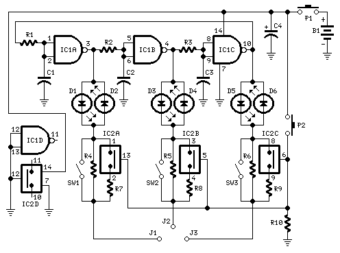
Tests transistors and diodes for polarity. A three-phase waveform is derived from the 350Hz ring-of-three oscillator formed by IC1A, IC1B, and IC1C, and applied to the device under test via the LEDs. The oscillator waveform enables each pair of...

U1 (555 in monostable mode) generates a square wave signal that corresponds to the input signal. This square wave is then sent to the mixer (U2) along with the original signal for mixing, effectively functioning as a frequency doubler....
Tired of experimenting with capacitors? It's time to explore supercapacitors, which offer significant storage capabilities. This article provides instructions on building a small LED flashlight utilizing supercapacitors. A minimum voltage of 2 volts is necessary to illuminate the LED,...
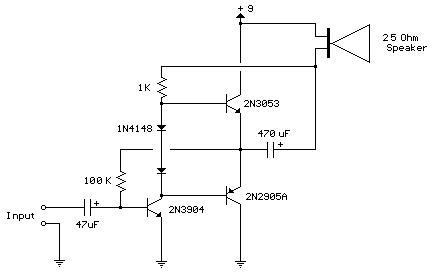
This circuit is similar to the previous one but employs positive feedback to enhance the amplitude delivered to the speaker. It was adapted from a small five-transistor radio that utilizes a 25-ohm speaker. In the prior circuit, the load...
Warning: include(partials/cookie-banner.php): Failed to open stream: Permission denied in /var/www/html/nextgr/view-circuit.php on line 713
Warning: include(): Failed opening 'partials/cookie-banner.php' for inclusion (include_path='.:/usr/share/php') in /var/www/html/nextgr/view-circuit.php on line 713