
IR S/PDIF Receiver
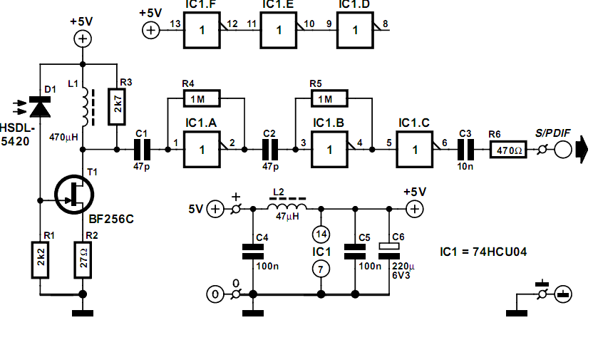
This circuit is designed to work in conjunction with the IRS/PDIF transmitter, forming a robust system for infrared communication. The IRS/PDIF transmitter converts digital audio signals into infrared light signals, which can be transmitted wirelessly. The IR receiver, on the other hand, captures these infrared signals and converts them back into audio signals for playback through speakers or other audio devices.
The circuit typically includes several key components: a photodiode or phototransistor as the IR receiver, an amplifier circuit to boost the received signal, and a decoder to interpret the signal and convert it into an audio format. The photodiode is positioned to receive the infrared signals emitted by the transmitter. When the infrared light hits the photodiode, it generates a small current that is proportional to the intensity of the light.
The amplifier circuit is crucial as it increases this small current to a level suitable for processing by the decoder. Operational amplifiers (op-amps) are commonly used in this stage to ensure that the signal is clean and strong enough for further processing. The output of the amplifier feeds into a decoder circuit, which may be a microcontroller or a dedicated audio decoder IC. This component interprets the digital signal and converts it into an analog audio signal.
The overall design of the circuit should also consider power supply requirements, ensuring that both the transmitter and receiver operate efficiently without interference. Additionally, careful layout and shielding may be required to minimize noise and ensure reliable communication between the transmitter and receiver.
In summary, this circuit provides an effective means of transmitting audio signals wirelessly through infrared light, utilizing a combination of photodetection, amplification, and signal decoding to achieve high-quality audio reproduction.This simple circuit proves to achieve surprisingly good results when used with the IRS/PDIF transmitter described elsewhere in this site. The IR receiver.. 🔗 External reference
Related Circuits
This project originated from a desire to experiment with traditional methods of radio construction that were popular approximately 70 years ago. The aim was to explore the performance that could be achieved using simple circuits that incorporate valves or...

This schematic represents a radio receiver circuit based on the TDA7088T, which is suitable for use in mono portable and pocket radios. The TDA7088T is a bipolar integrated circuit designed to operate with a minimal number of peripheral components...
Many amateur receivers are equipped with an S meter that does not operate logarithmically. The proposed circuit is intended to enhance such receivers. Although integrated circuits like the CA3089 or CA3189 are not commonly used today, they play a...
I describe a simple direct conversion receiver, designed for QRSS and DFCW communications, as a companion to ARGO or SPECTRAN programs. The intention is not to surpass the performance of professional or commercial ham radio receivers; rather, the goal...

The individual was not inclined to create and program the timing controller for the PCB laser printer. They recalled having a laser tag gun that had been misaligned during a previous disassembly. The device in question is a Nerf...
The CAMD CM8888 8888-2 is a fully integrated DTMF transceiver that features adjustable guard time, automatic tone burst mode, call progress mode, and a fully compatible interface for 8051 and 8086/8 microprocessors. It is manufactured using advanced CMOS technology,...