
IR2110 for forward inverter system schematic

In forward inverter applications, the IRZ110 component is integral for signal reception, specifically when interfaced with the IR 2110. The IR 2110 is responsible for generating the pulse signals that dictate the operational phases of the inverter. The inverter operates by alternating between high-output (HO) and low-output (LO) phases, which are crucial for controlling the flow of electricity through the load. When the HO output is activated, the voltage across the load (VF) is allowed to conduct, facilitating current flow. Concurrently, if the LO output is also active, it creates a condition where both outputs are conducting, enabling efficient power transfer.
The inverter's design ensures that when the HO output is deactivated, the LO output takes over to maintain the flow of current, preventing interruptions in power delivery. This switching mechanism is essential for applications requiring stable voltage and current levels, particularly in inductive loads where the behavior of current flow is critical. The inverter's ability to manage these transitions effectively is achieved through precise control of the output phases.
Additionally, the sampling circuit for load current (HL) plays a vital role in monitoring and protecting the system from overcurrent conditions. This protection circuit is designed to detect excessive current levels and respond accordingly to prevent damage to the inverter components. The overall functionality of the inverter system is enhanced by this protective measure, ensuring reliable operation under varying load conditions. The forward inverter configuration is thus optimized for performance and safety in high-voltage applications.In the forward inverter system applications: IRZ110 for receiving such a line when the line shown in Figure 12-39, in this application, the next channel on the channel IR 2110 and shared an input into the pulse signal, which determines the HO and LO-phase output. Workers of the inverter as a principle, when the channel output HO is high, VF, conduction, this time due to the next one channel output LO is also high, so VF, conduction, VF, shutdown, VF. conduction, electricity flows through the high voltage power supply HV, field scattered and directly load transistor VF ,, Z and field-effect transistor VF, circulation.
The LO output when the upper channel and the lower channel HO output is low level, VF, and VF. Off, VF. Conduction, inductive load Z resumed flow path for the VF. , Z and VD. To a high voltage power supply. Thus, this inverter input control no Cang signal is high or low in the load current and voltage section Z as a positive direction (left to right). So called forward inverter din, the figure HL load current sampling part. Its role is to provide a protection circuit overcurrent protection signal, " over-current protection.
Related Circuits
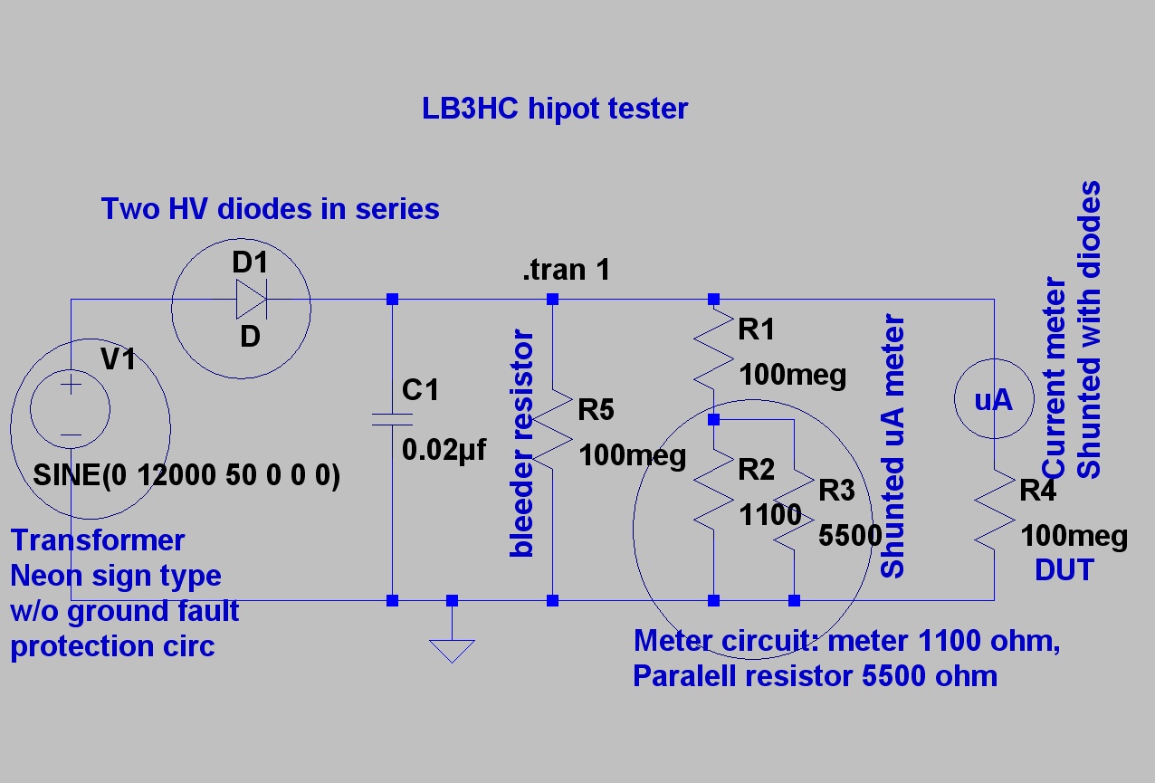
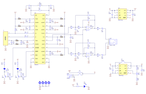
The design is based on concepts from K8CU and AG6K, but the circuit has been simplified and uses different components. The mechanical encapsulation has also been modified. LTspice was utilized to verify the tester prior to construction. The schematic...
Construct a variable 5A, 2V to 25V regulated power supply using the LM338 adjustable regulator. A power supply schematic and parts list are provided here. The LM338 adjustable voltage regulator is a versatile component capable of providing a regulated output...
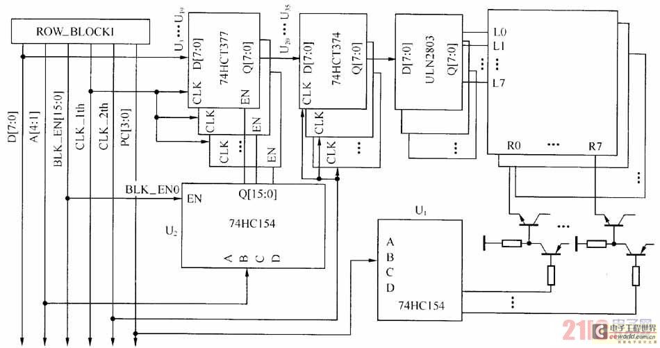
The large-scale LED display system utilizes a line-by-line scanning method and outlines the driving mechanisms to reduce hardware costs. It employs a 1/16 non-interlaced scanning mode, accommodating a total of 16 LED display panels. The schematic diagram of the...
The APX9132 integrated circuit is an ultra-sensitive, pole-independent Hall-effect switch featuring a latched digital output. It operates within a voltage range of 2.5 volts to 3.5 volts, and its unique clocking scheme reduces average power consumption. The output activates...
Creating a sound card is no longer a complex task. By utilizing the PCM2702 integrated circuit from Burr Brown / Texas Instruments, it is possible to design a fully functional USB sound card. This sound card can be powered...
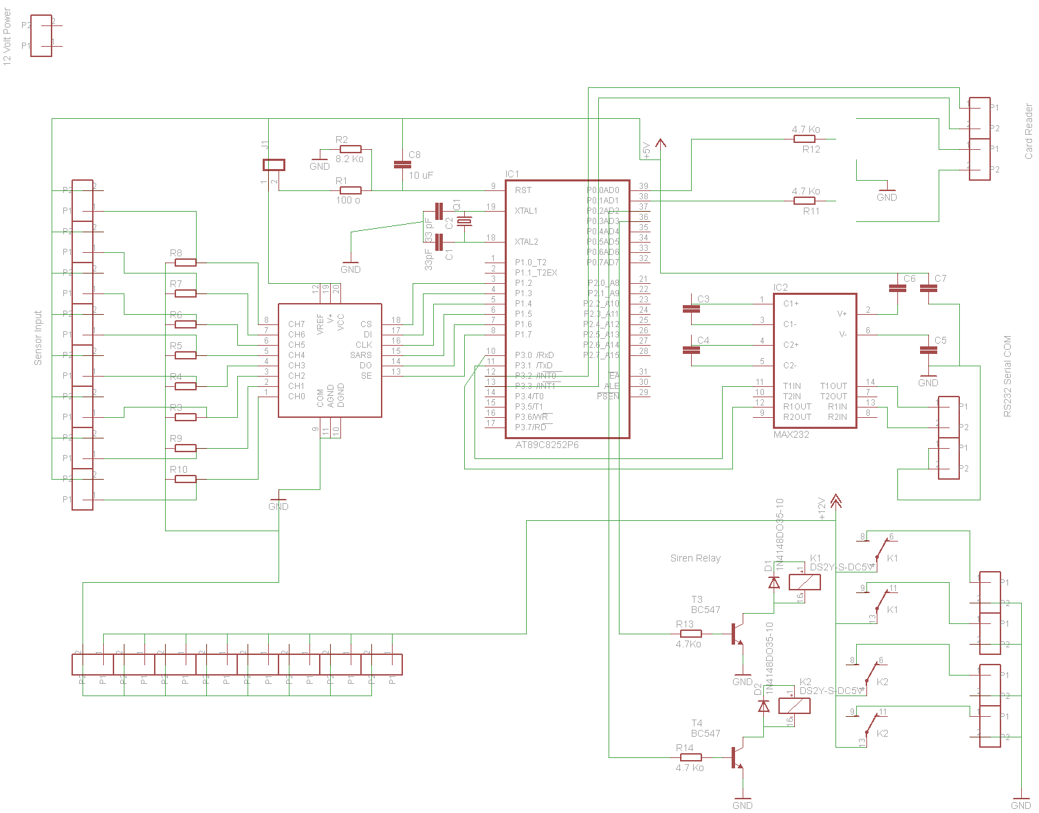
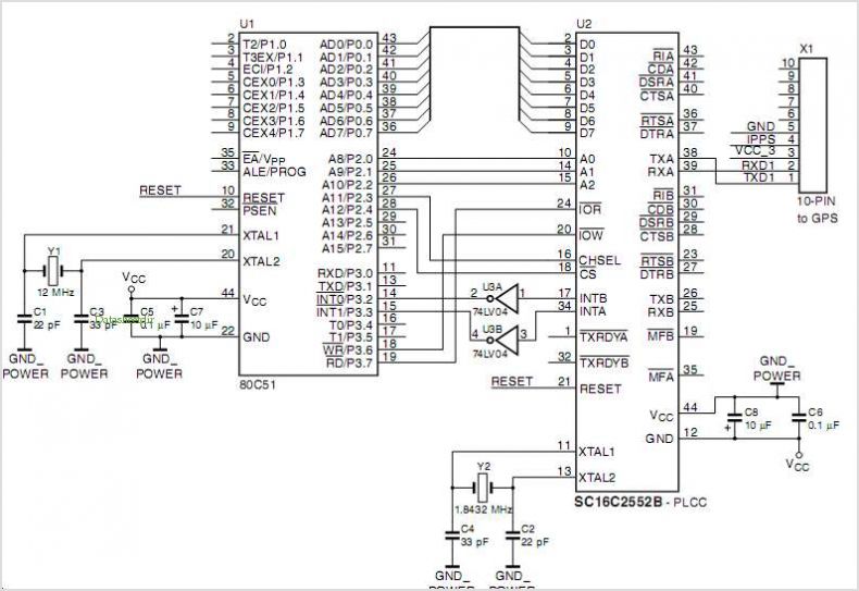
The fundamental design of this project employs an Atmel AT89S8252-24PC Microcontroller, which features 2KB of EEPROM for runtime data storage. An ADC0838CCN analog-to-digital converter will be utilized to process up to eight inputs from sensor devices, including passive infrared...