
Schematics USB Sound Card with PCM2702 PCB
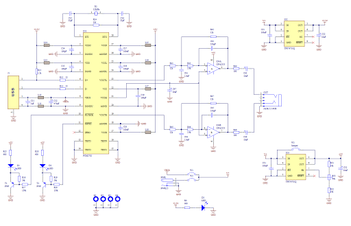
The circuit design for the USB sound card centered around the PCM2702 IC is efficient and user-friendly. The PCM2702 serves as the primary digital-to-analog converter (DAC), converting digital audio signals from the USB interface into analog signals suitable for output through the stereo jack. The choice of power supplies is critical, as the device requires both a 3.3V and a 5V supply to operate optimally. The TPS76733Q and TPS76701Q LDOs are selected for their reliability and performance characteristics, ensuring stable voltage outputs that are essential for audio fidelity.
The implementation of ferrite beads is a common practice in audio circuits to suppress electromagnetic interference. Their placement before the power pins of the PCM2702 and along the USB power lines helps to mitigate high-frequency noise that could adversely affect audio quality. The option to substitute these beads with zero-ohm resistors provides flexibility in the design, allowing for adjustments based on component availability.
The low-pass filter, utilizing the OPA2353UA op-amp, is a crucial component in managing the audio output. By configuring the op-amp in a 2nd-order low-pass filter arrangement, it effectively attenuates high-frequency noise and smooths the audio signal, thereby enhancing the listening experience. The filter design may include various resistor and capacitor values to tailor the cutoff frequency to the specific audio application.
LED indicators provide visual feedback on the operational status of the sound card. The power indicator (D3) ensures users are aware of power availability, while the audio activity indicators (D1 and D2) inform users of the data transmission status, adding an additional layer of usability to the design. Overall, the schematic for this USB sound card is straightforward yet effective, making it an excellent project for those interested in audio electronics.Make a sound card is no more a complex issue. If you use great IC PCM2702 from BURR BROWN / Texas Instruments you can create a fully functional USB sound card. This sound card can be powered from USB port and has one stereo output. You don ½t need to install any driver for Windows XP and Vista, because they are already inside. This is really plug and play. PCM2702 needs only few additional parts to work. The schematic is not complex. Sound card can be powered directly from USB port (jumper W1) or from external power supply (jumper W3). PCM2702 needs two power supply 3. 3V (3V-3. 6V) and 5V (4. 5V-5. 5V). I used fixed output voltage LDO TPS76733Q for 3. 3V (IO2) and adjustable output voltage LDO TPS76701Q for 5V (IO3). Both LDO are produced by TI, I used this because I had it in my drawer. Any similar LDO can be used. Output voltage of IO3 should be set to little bit lower than input voltage to allow LDO good stabilization, in my case output voltage is set to 4.
8V. Output voltage can be set by adjustable resistor R33. In case of low power supply, IO3 can be shorted by jumper W3. LED D3 signalizes power on. Small ferrite beads are placed before all power pins of PCM2702 and in Vbus and GND of USB. These small beads reduce high frequency hum. I had a problem find this small SMD ferrite beads in local stores but finally I acquire few of them from old hard drive. They are not absolutely necessary, you can use zero ohm resistors instead of them. Low-pass filter is placed in output signal path to reduce sampling frequency. An OPA2353UA dual op amp is configured as a stereo 2nd-order low-pass filter. Led diode D1 is illuminated when PCM2702 plays audio data received from the USB bus. Led diode D2 is illuminated when USB bus suspends audio data transmission to the PCM2702. 🔗 External reference
Related Circuits
In this circuit, the alarm activates under four different conditions: 1. When light falls on LDR1 (located at the entrance). 2. When light on LDR2 is obstructed. 3. When door switches are opened or a wire is cut. 4....
The concept of distributed active RIAA correction and the use of negative feedback to linearize the input stage is appealing. However, the original design by Collin has significant flaws, including poor power supply rejection ratio (PSRR) in the input...
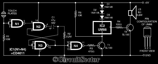
This circuit diagram illustrates a touch-sensitive musical bell based on the UM66 melody generator IC. The design incorporates a CMOS IC CD4011 and features a pair of touch plates. When these plates are briefly bridged by a hand, the...
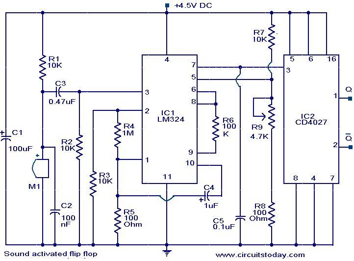
This circuit allows the output pins of a Flip Flop IC to be toggled using sound. A condenser microphone captures the sound, and the first two operational amplifiers in the LM324 IC amplify the signal. The third operational amplifier...
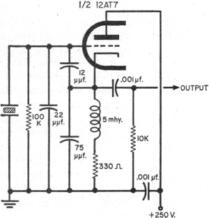
The fundamentals of crystals have not changed since this article appeared in a 1960 edition of Popular Electronics. The methods for growing, cutting, and packaging crystals have evolved significantly. Understanding their operation at the atomic level has also advanced...
This sound level measuring device circuit can be used to control the intensity of a sound recording in the field of a disco. It has five measurement ranges between 70 and 120 dB, with a measurement accuracy of 0.5...