
Large-scale LED display system hardware structure and principle

The large-scale LED display system is engineered to optimize both performance and cost-effectiveness through its innovative design. The line-by-line scanning method employed enables efficient utilization of resources while maintaining high-quality image rendering. By adopting a non-interlaced scanning mode, the system minimizes flicker and enhances visual clarity across the entire display.
The architecture of the display modules is meticulously designed to ensure that each 64x32 dot matrix is effectively managed. The division into two sections facilitates easier data management and allows for a more organized approach to data latching. The multiplexing strategy, utilizing a 1-to-4 intersection combined with a 16 intersection decoder, ensures that the data flow is efficiently controlled, allowing for seamless transitions between the upper and lower sections of the display.
The implementation of a two-step latching mechanism is crucial for maintaining data integrity during display operations. In scenarios where the dot matrix experiences failure, this mechanism prevents visual artifacts such as tailing, thereby ensuring a consistent user experience. The master control board plays a vital role in this process, as it dictates the timing and synchronization of data transmission, ensuring that the display operates smoothly and efficiently.
The use of a parallel bus for the second latch significantly enhances data transmission capabilities, allowing for rapid updates to the display without compromising performance. This approach not only improves response times but also reduces the overall complexity of the system.
The cascading connection strategy among driver modules further enhances the system's functionality. By allowing for sequential strobing of the first step latches, the design promotes scalability and flexibility, making it easier to integrate additional modules as needed. This adaptability is essential for large-scale installations where varying display sizes and configurations may be required.
Overall, the design of the large-scale LED display system is a testament to modern engineering principles, combining efficiency, reliability, and adaptability to meet the demands of contemporary display technology.The large-scale LED display system adopts the line by line scan and lists the driving means to save the expenses of hardware, it adopt 1/16 it is non-interlaced scanning mode, LED display screens large-scales whole it last 16 pieces all right. The picture, in order to reveal the schematic diagram of the driver module. Each display module is that a small dot matrix of 64* 32 picture element is rejected, is divided into two parts, each 16 lines from head to foot, every part has 8 groups to list the latch of data. Upper and lower two part multiplex 1 4 the intersection of son and 16 the intersection of Decoder and U1, strobe, drive 1/16 line by line scan reveal, and need 16 groups to list to drive the latch to latch and list the view data.
Adopt and run side by side totally, at the time of line data transmission mode, needing can list the latch to make to strobe with a Decoder U2s. Need to use the two-step latch to latch and list the view data in sunset when the dot matrix is broken, otherwise will reveal the tailing phenomenon.
Expicity data store the second latch in this time, master control board write down party, want expicity data go on, list data, break rejecting the intersection of end and the intersection of first step and latch, party take after the expicity data transmission instantly, latch, get the second latch export and strobe, drive row display the next together. Adopt second latch of parallel bus under the way, still than competent to transmit, change with data into scheme economy of parallel output Zhyuan have.
Reveal that uses and misplaces the cascade connected thinking at the time of horizontal cascade between the driver module, make it have good commonability and but embeddability. Use and misplace the cascade connected thinking, make the Decoder U2 of first step latch on the driver module of horizontal cascade connected display can be strobed sequentially, this Decoder can strobe first step and list the latch of the data sequentially.
The first step on so horizontal cascade-connected screen can be regarded as a section of serial memory cell when listing the latch of the data, this is a foundation of using DMA parallel data transmission control. 🔗 External reference
Related Circuits
This simple counter can be used to count pulses, as the basis for a customer counter (like you see at the doors of some stores), or for anything else that may be counted. The circuit accepts any TTL compatible...
This article discusses the design of an LED driver for automotive rear lights. It demonstrates that dimming is most effectively accomplished using pulse-width modulation (PWM) in conjunction with an LED driver integrated circuit (IC) that removes the requirement for...
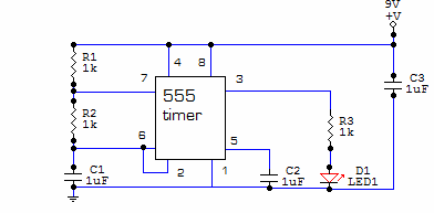
This circuit is built around one of the most popular timer integrated circuits, the 555 timer. It will flash the LED on and off at regular intervals. From left to right, the two resistors and the capacitor set the...
This LED thermometer is designed for in home use, to read temperatures between about 60 and 78 degrees Fahrenheit. It is based around a precision temperature sensor IC, the LM34DZ. This sensor require no calibration and can measure temperatures...
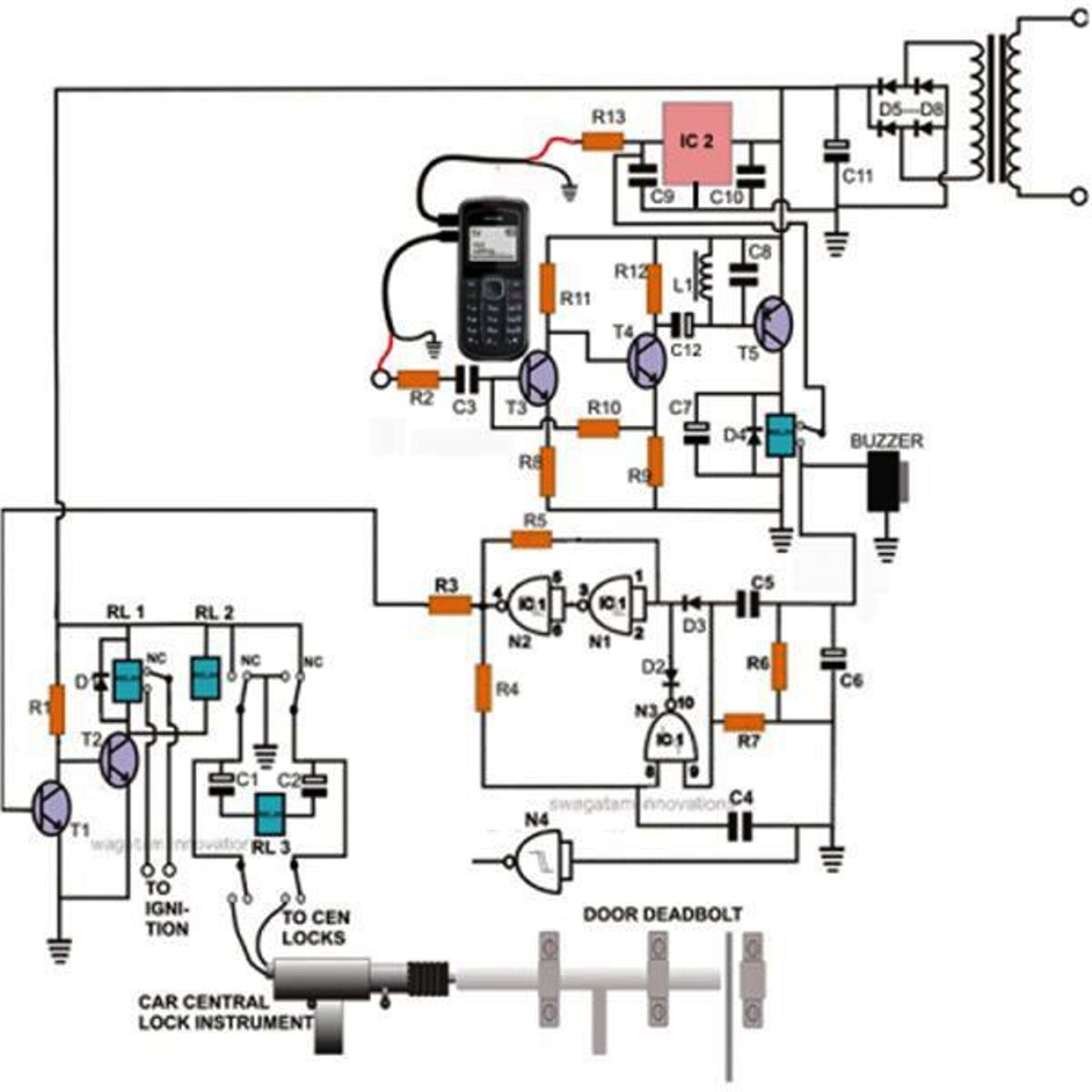
Controlling a door lock through a personal cell phone has become remarkably straightforward. This project outlines the construction of a simple electronic circuit that transforms a conventional door lock into a high-security lock, which can now be operated via...
If we have a lot of parallel telephones on a telephone line, we needed a unit that will have the possibility of showing if somebody of the telephone has raised the earphone. Our this possibility give the circuit. The...