
irf44 mosfet based on 100 watt

This inverter circuit is designed to convert DC voltage into a stable AC voltage, specifically 230V, suitable for various applications. The circuit's operation frequency, set by the variable resistor (VR1), allows for adjustments to accommodate different load requirements, with a standard setting of 60 Hz, suitable for most household appliances.
The choice of transformers is crucial; off-the-shelf options are available, but for specialized applications or higher efficiency, custom-wound transformers may yield better results. The transformer must be rated appropriately for the expected load to ensure reliable operation.
To enhance the power handling capability of the inverter, additional MOSFETs can be paralleled. This configuration allows for the distribution of the current load across multiple devices, reducing heat generation and improving overall efficiency. Care must be taken to ensure that the MOSFETs are matched in characteristics to avoid uneven current distribution, which could lead to failure.
Incorporating a fuse into the power line is essential for safety. The recommended rating of 10 Amps for every 100 watts of output serves as a guideline to protect the circuit from overload conditions. The fuse will disconnect the circuit in the event of a fault, preventing damage to the components and ensuring safe operation.
Furthermore, maintaining a continuous load during operation is critical. This practice stabilizes the inverter's performance and prevents potential damage caused by sudden changes in load conditions. The power leads must be made from heavy gauge wire to accommodate the high current draw, ensuring minimal voltage drop and heat generation during operation. Proper sizing of these leads is vital for maintaining efficiency and safety in high-power applications.This inverter circuit can offer a really stable 230V Output Voltage. Frequency of operation is decided by a VR1 and is generally set to 60 Hz. varied off the shelf transformers can be used. Or Custom wind your own for best results. additional MosFets can be paralleled for higher power. it`s recommended to own a Fuse within the Power Line and to perpetually have a Load connected , while power is being applied. The Fuse ought to be10 Amps per one hundred watts of output. the ability leads must be serious enough wire to handle this High Current Draw. 🔗 External reference
Related Circuits
This compact switching power supply utilizes a Schmitt trigger oscillator to control a switching transistor, which provides current to a small inductor. When the transistor is activated, energy accumulates in the inductor, and this energy is subsequently released into...
This circuit is based on the State Variable Band Pass Filter, incorporating amplitude-limited regenerative feedback. The State Variable Band Pass Filter (SVBPF) is a versatile filter design that allows for simultaneous control over the center frequency, bandwidth, and gain. This...
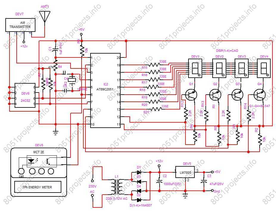
RF based Automatic meter reading, or AMR, is the technology of automatically collecting data from energy meter and transferring that data to a central database for billing and/or analyzing. This means that billing can be based on actual consumption...

The circuit design is relatively straightforward. It features a Voltage Controlled Oscillator (VCO) utilizing the ICL8038 along with supplementary components, a sine and triangle output stage using the LT1210, and a CMOS-compatible output stage driven by the MOSFET driver...
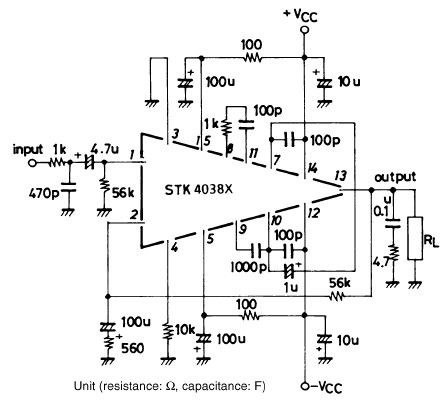
The STK4038-based 60-watt audio amplifier circuit project utilizes the STK4038X audio amplifier IC, designed to create a straightforward yet high-power and efficient audio power amplifier. Manufactured by Sanyo Corporation, this circuit delivers an output power of 60 watts with...
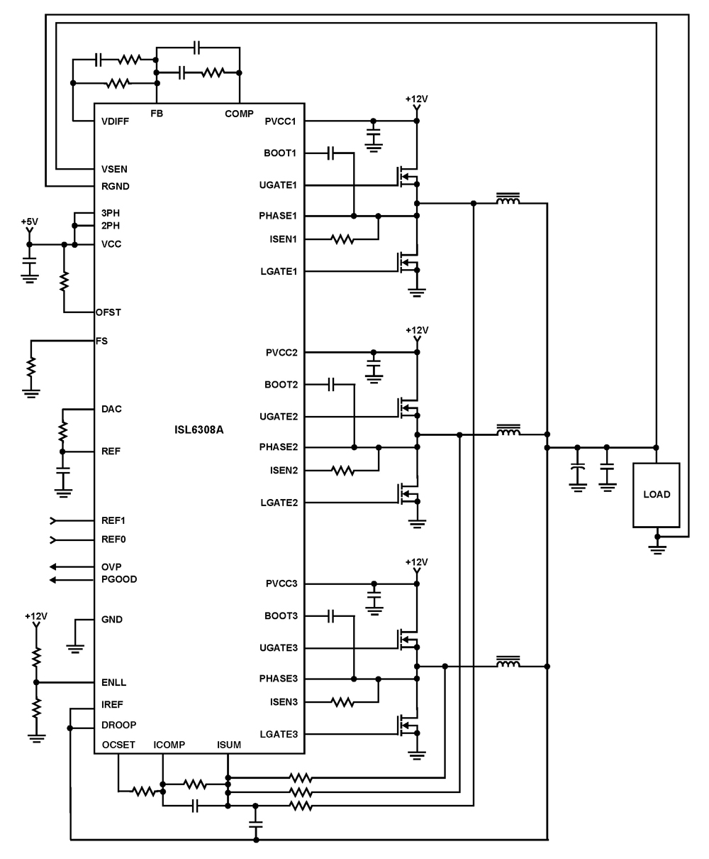
The ISL6308A is a three-phase PWM control integrated circuit (IC) equipped with built-in MOSFET drivers. It delivers precise voltage regulation suitable for various applications, including high current low voltage point-of-load converters, embedded systems, and other general low voltage medium...