
ICL8038-based Oscillator
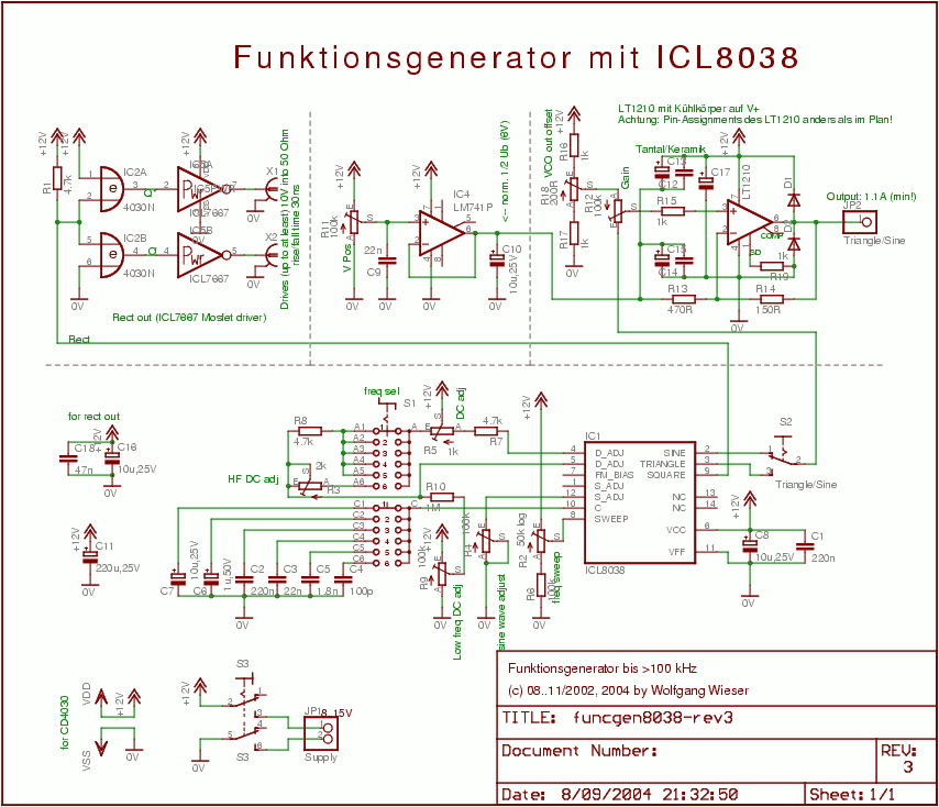
The circuit is designed to provide a versatile and stable waveform generation system suitable for various applications. The primary components, including the ICL8038 and LT1210, are chosen for their performance characteristics, ensuring that the oscillator can deliver high-quality sine and triangle wave outputs. The inclusion of user-adjustable components allows for customization based on specific application needs, while the attention to detail in the design, such as the bypassing of the MOSFET driver, helps maintain signal integrity. The use of CMOS logic ensures compatibility with digital systems, making this circuit a practical choice for modern electronic designs.The circuit is a fairly easy design: It consists of the actual VCO (ICL8038 with supplement parts), the sine and triangle output stage (LT1210) and the CMOS-compatible output stage using the MOSFET driver chip ICL7667. The ICL8038 and all parts around on the lower half of the sheet make up the actual oscillator which is a modified design based on
one of the application examples in Intersil `s data sheet. There is a large 6-stage switch (S1) to select the major frequency and a logarithmic potentiometer (R2) for minor frequency selection. I discourage implementing the oscillator as shown in the above sheet because most of the other potentiometers turned out to be without significant enough effect on the output wave form to jusify their application.
Furthermore, duty cycle adjustment will not keep a 50% ratio over all frequencies. The CD4030 on the left top is used as CMOS-logic signal preconditioning feeding the MOSFET driver IC ICL7667 as output stage for the complementary square wave output. The application of the two XOR gates has the advantage that it can supply a sqare wave and its complement without time offset between them (because CMOS has balanced raise and fall times).
Use a bypass capacitor near the ICL7667 device as it can draw quite strong currents and is capable of driving into 50Ohm up to at least 10V resulting in rise/fall times of 30ns. So, I`m now entirely satisfied with the digital output. The industry-standard LM741 in combination with R11 is used to adjust the sine/triangle offset level.
(Hint: You should probably use something better here - especially more output current cannot hurt. ) Since this oscillator is single-supply, it comes handy that you can change the "zero level" of the wave output; you will normally adjust that to half of the supply voltage. R11 is meant to be available to the user. The actual sine/triangle output amplifier was a bit hard to find because it should be able to drive 1A while still not degenerating signal wave form at some hundred kHz.
After some searching, I found the ADSL line driver LT1210 from Linear Technology. Being an ADSL line driver, it has a high GBP and high slew rate while providing the required output current (1. 1A guaranteed) at all frequencies in question. The part can be obtained e. g. from BG rklin. It turned out that this quick current feedback amplifier required very good DC decoupling/bypassing capacitors in order not to start oscillating of its own (at frequencies up to 40MHz).
It took me a lot of time to get it work properly; but once that is achieved, the amplifier shows very good performance. (Note: The current implementation is not yet perfect as I noted some months later: It may still start oscillating for parts of the period when driving some special loads.
) R18 is used to trim the VCO output offset from the ICL8038 (about half supply voltage). R12 is meant for the user as gain adjustment to tune the sine/triangle amplitude from zero to more than supply voltage (resulting in wave tips being cut off). The maximum gain is trimmed by R13/R14 and care sould be taken to use proper values (consult LT1210`s data sheet for details).
🔗 External reference
Related Circuits
A quadrature oscillator is a type of phase shift oscillator that produces two sine wave signals, with one signal shifted by 90 degrees from the other. The quadrature oscillator is commonly used in various applications such as signal processing, communications,...

This oscillator may contain several switched crystals to provide channelized operation. A buffer amplifier may be added if desired. The oscillator described is designed to utilize multiple switched crystals, enabling it to operate across various frequency channels. This feature is...
This Wien bridge oscillator is straightforward and, like all Wien oscillators, exhibits low distortion. The resonance frequency can be easily adjusted. The Wien bridge oscillator is a type of electronic oscillator that generates sine waves. It is based on the principle...
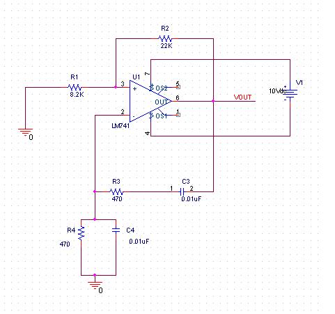
A practical project is being conducted using the LM741 operational amplifier configured as a Wien bridge oscillator. The component values are specified as follows: C1 = C2 = 0.01 µF, R1 = R2 = 3 kΩ, Rf = 2...
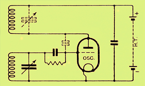
The congestion of the ether is increasing, prompting ongoing efforts to extend communication channels to higher frequencies. Wavelengths as short as 12 meters are now common, but operating below this presents significant challenges. At approximately one meter, the oscillation...
A type of relaxation oscillator comprising two stages that are interconnected such that the input of one stage is derived from the output of the other. This configuration essentially consists of two amplifiers cross-coupled with regenerative feedback in its...
Warning: include(partials/cookie-banner.php): Failed to open stream: Permission denied in /var/www/html/nextgr/view-circuit.php on line 713
Warning: include(): Failed opening 'partials/cookie-banner.php' for inclusion (include_path='.:/usr/share/php') in /var/www/html/nextgr/view-circuit.php on line 713