
Isolated Full-duplex Rs232 Interface

This self-powered interface circuit serves as a critical component in ensuring safe and reliable communication between a PC and external devices through the serial port. The design emphasizes electrical isolation, which is paramount in applications where different voltage levels are present or where ground loops could introduce noise or damage to the equipment.
The circuit utilizes standard serial communication signals, specifically the Data Terminal Ready (DTR) and Request to Send (RTS) lines, to derive the necessary power for the PC side of the interface. This innovative approach eliminates the need for an external power supply, enhancing the circuit's portability and ease of integration into existing systems. By setting the RTS line to a logic low state and the DTR line to a logic high state, the circuit ensures that the power levels are appropriately configured for operation.
The isolation is achieved using two integrated circuits, IC U1 and IC U2, which serve to separate the TxD (transmit data) and RxD (receive data) lines, respectively. This isolation is essential for protecting the PC from potential voltage spikes or transients that may occur on the connected equipment side. The output from the isolator is compatible with TTL logic levels, making it suitable for interfacing with a wide range of microcontrollers and digital systems.
To enhance signal integrity and provide visual feedback, IC U3 buffers the signals from the opto-isolators. It also drives LEDs that indicate data transmission activity, providing an intuitive means for users to monitor the status of the communication link. The circuit has been rigorously tested to ensure reliable performance at a baud rate of 19.2k, making it suitable for various applications that require serial communication with strict isolation requirements. Overall, this interface circuit is an effective solution for achieving safe and reliable data transfer between a PC and isolated equipment.This self powered interface circuit electrically isolates the TxD and RxD lines from the PC serial port and protect the PC from direct connection to hazardous voltages. The isolator is intended to provide electrical isolation between a computer and the equipment connected to its serial port.
This can be necessary when the target system works at a completely different voltage level, or when earth loops must be avoided. Figure 1 shows how the electrical isolation is achieved. Connector K1 is linked to the serial port of the PC, power to the PC side of the circuit is derived from the signal lines DTR and RTS. Positive supply is derived from RTS and -ve one from the DTR line, therefore it is necessary for the user program to set the RTS status to logic zero & DTR to logic one in order to get the proper supply levels at the output.
IC U1 is used to isolate the TxD line while IC U2 isolates the RxD line. The other side of the isolator carries TTL levels. This side is powered by the target system power supply. IC U3 is used to buffered the signals for the opto isolators and also drives the data indicating LEDs. The interface has been tested at the baud rate of 19. 2k baud. 🔗 External reference
Related Circuits
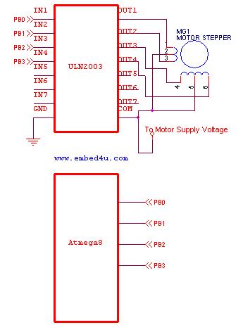
This tutorial utilizes the ATmega8 microcontroller with a 4 MHz crystal oscillator and unipolar stepper motors. The ULN2003, a Darlington pair driver integrated circuit, is employed for motor control. The ATmega8 microcontroller is a versatile 8-bit device from the AVR...
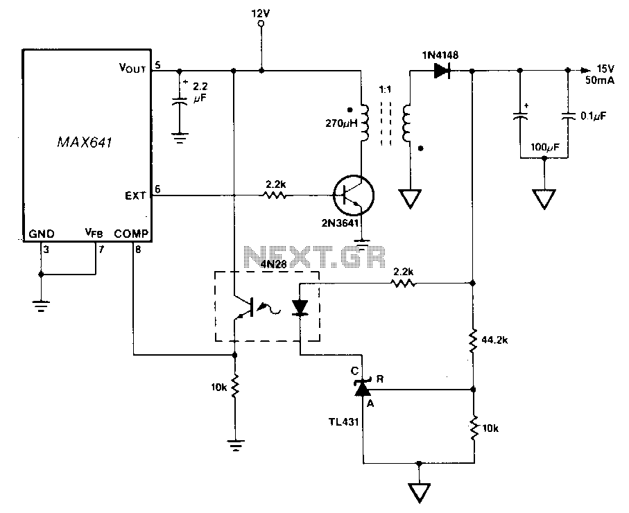
In this circuit, a TU31 shunt regulator is utilized to monitor the output voltage. The TU31 activates the LED of a 4N28 optocoupler, which delivers feedback to the MAX641 while ensuring isolation between the input voltage of +12 V...
One of the most effective communication methods to be implemented in a digital system is the use of the RS232 serial line. The microcontroller 89S51 is equipped with a UART, allowing it to perform serial communication at RS232 levels...
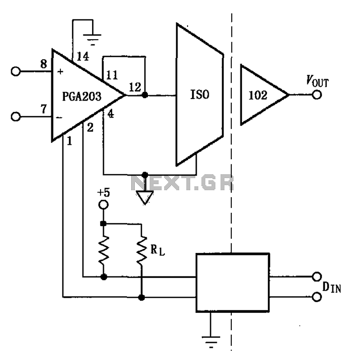
The PGA203 and isolation amplifier IS0102 form an isolated programmable gain instrumentation amplifier circuit. The PGA203 amplifies the input signal, and the output from the isolation amplifier IS0102 is VOUT. Additionally, a DIN digital optocoupler is used for the...
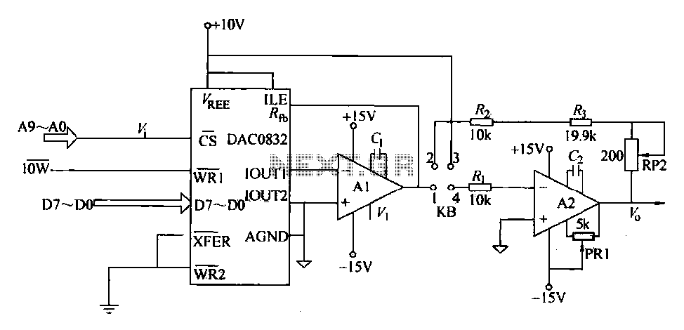
The DAC0832 is a digital-to-analog converter (DAC) chip designed for integration with computer bus systems. It features an 8-bit resolution and operates with a single power supply ranging from 5 to 15 volts. The device is compatible with TTL...
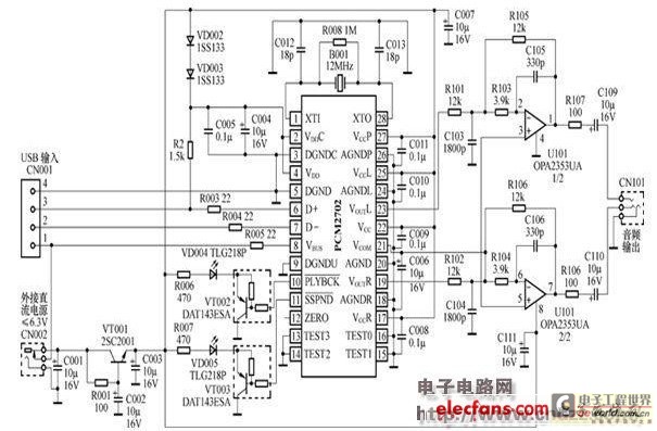
The peripheral circuit is straightforward, consisting of a DAC schematic circuit diagram for a USB interface that utilizes the PCM2702. The output of the circuit can be directly connected to a power amplifier and is capable of driving headphones...