
DAC0832 single - bipolar voltage output interface circuit
The DAC0832 is a versatile 8-bit digital-to-analog converter that facilitates the conversion of digital signals into corresponding analog voltages. It is particularly suited for applications requiring straightforward integration with microcontrollers and computer systems due to its TTL compatibility and simple interfacing capabilities.
The device operates on a single power supply, simplifying the design and reducing the number of required components. The input levels are compatible with standard TTL logic, making it easy to connect to digital systems without additional signal conditioning.
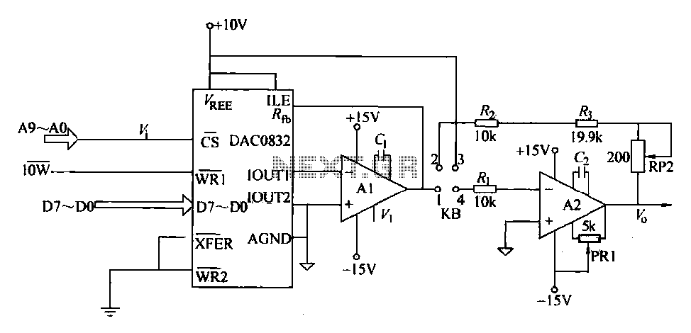
The output configuration of the DAC0832 is flexible, allowing for both unipolar and bipolar voltage outputs. In unipolar mode, the output voltage ranges from 0 to 10 volts DC, which is suitable for many applications that require a positive voltage output. To configure the DAC for unipolar operation, short connections are made between specific pins, namely KB1-4 and KB2-3.
In bipolar mode, the DAC0832 can output voltages ranging from -10 volts to +10 volts DC. This mode is beneficial in applications where both positive and negative voltages are required. The configuration for bipolar output is achieved by appropriately shorting the KB connections, ensuring that the device operates within the desired voltage range.
The interface circuit for the DAC0832 includes connections for data input and control signals, which are critical for its operation. The XFER and WR2 control signals are grounded, indicating that they are inactive during standard operation. The ILE signal, when set high, enables the internal logic of the DAC to process incoming digital data.
In summary, the DAC0832 is a highly functional and adaptable digital-to-analog converter capable of meeting the needs of various electronic applications, from simple signal generation to more complex systems requiring precise analog outputs. Its ease of integration, coupled with the ability to select between unipolar and bipolar outputs, makes it a valuable component in the design of electronic circuits.DAC0832 is a memory device having two input engrave a D/A converter chip, can be connected directly to the computer bus. Its main properties are as follows: 8-bit resolution; s ingle power supply (5-15v) i input level and TTL logic level compatible. D/A converter circuit output current and voltage outputs are divided into two kinds. Unipolar output voltage bipolar fork into two, as shown in Figure 27-11 DAC0832 interface circuit for the single/bipolar voltage output is shown. Figure, DAC0832 data input and computer system data bus. XFER, WR2 control signals are grounded, ILE pick high. Short column KB short of 1-z when connected. Compared with unipolar voltage (O-lOV DC) output; KB of l-4 and 2-3 short-circuited, for the dual polarity (-10V-O- + 10V DC) output,
Related Circuits
This circuit is designed to detect microwave sources, such as microwave ovens, satellite communication devices, and mobile phones. It provides audio-visual indications upon detecting microwaves in the gigahertz band, which encompasses frequencies between 2 GHz and 300 GHz. Microwave...
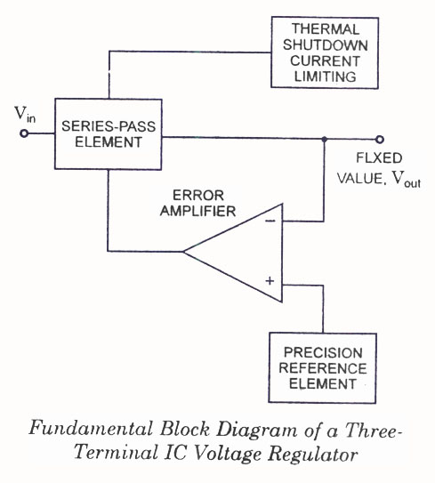
IC Voltage Regulators - Circuit diagram and block diagram of linear, fixed, adjustable (positive and negative), and switching voltage regulators. IC voltage regulators are essential components in electronic circuits, providing stable output voltages from a varying input voltage source. They...
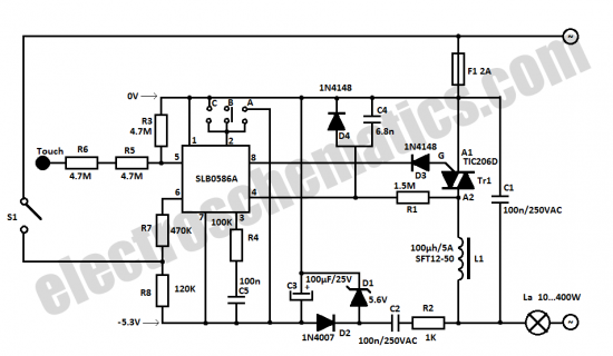
The SLB0586A integrated circuit from Siemens can be utilized to construct a straightforward touch light dimmer circuit, enabling the user to modify the intensity of a lamp. This circuit also incorporates a TIC206D component. The SLB0586A is a specialized touch-sensitive...

At the input of the operational amplifier, a resistor-diode network can be constructed to create a square-law function conversion circuit. This resistor-diode network acts as a voltage divider, where the input voltage variations lead to different partial pressures. The...
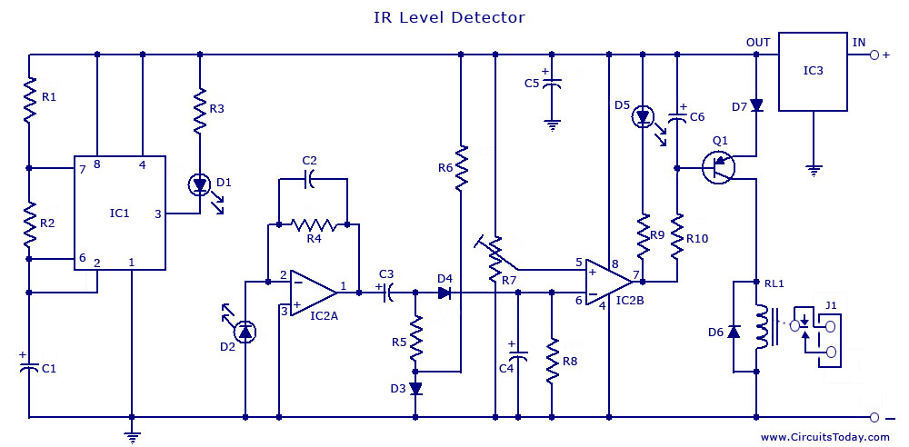
The circuit illustrates the use of a 555 Timer IC in an infrared (IR) detector configuration. It features a duty cycle of 0.8 milliseconds, a frequency of 120 Hz, and a peak current of 300 mA. The 555 Timer IC...
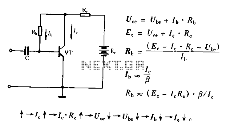
Bias voltage negative feedback circuit The bias voltage negative feedback circuit is a crucial component in various electronic applications, particularly in amplifiers and oscillators. This circuit is designed to stabilize the operating point of a transistor or operational amplifier by...