
DAC schematic diagram of the USB interface formed by PCM2702

The described peripheral circuit features a Digital-to-Analog Converter (DAC) based on the PCM2702 chip, which is commonly used for USB audio applications. The PCM2702 integrates USB audio processing, allowing it to convert digital audio signals from a USB source into analog signals. The circuit diagram typically includes essential components such as capacitors, resistors, and possibly an op-amp to manage signal integrity and amplification.
The output stage of this circuit is designed to interface directly with a power amplifier. This allows for seamless integration into audio systems, providing a straightforward path for audio signals to be amplified for driving speakers or headphones. The ability to drive headphones with an impedance greater than 32 ohms indicates that the circuit can provide sufficient output power, ensuring that the audio is loud enough for typical listening levels without distortion.
In practical applications, the circuit may include additional features such as volume control, filtering to reduce noise, and protection mechanisms to safeguard against overcurrent conditions. The layout of the circuit should be optimized for minimal signal loss and interference, with careful routing of the power and ground lines to maintain audio fidelity.
Overall, this DAC schematic serves as a fundamental building block for USB audio systems, enabling high-quality sound reproduction while maintaining compatibility with various audio devices.Peripheral circuit is very simple, it is DAC schematic circuit diagram of the USB interface which adopts PCM2702 to make the picture, the Ausgang of circuit can be connected with the power amplifier directly, can drive earphone of more than 32 ohms too. 🔗 External reference
Related Circuits
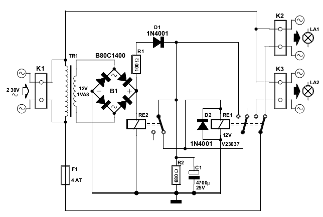
The normal operation of the light switch provides gentle illumination (LA1). To increase the brightness, simply turn the switch off and then back on again within one second. The circuit will revert to the gentle light setting if switched...
USB HID is a specification that encompasses devices such as mice and keyboards. It features a GPL-based driver that allows the implementation of USB on an AVR microcontroller without the need for specialized hardware. Additionally, there is the AVR309...
CMOS interface circuit with PMOS cross-coupled PMOS integrated circuit featuring high input impedance, where the input current can be ignored. The CMOS and PMOS interface circuit is illustrated in the accompanying figure. The CMOS interface circuit utilizing PMOS cross-coupled configurations...
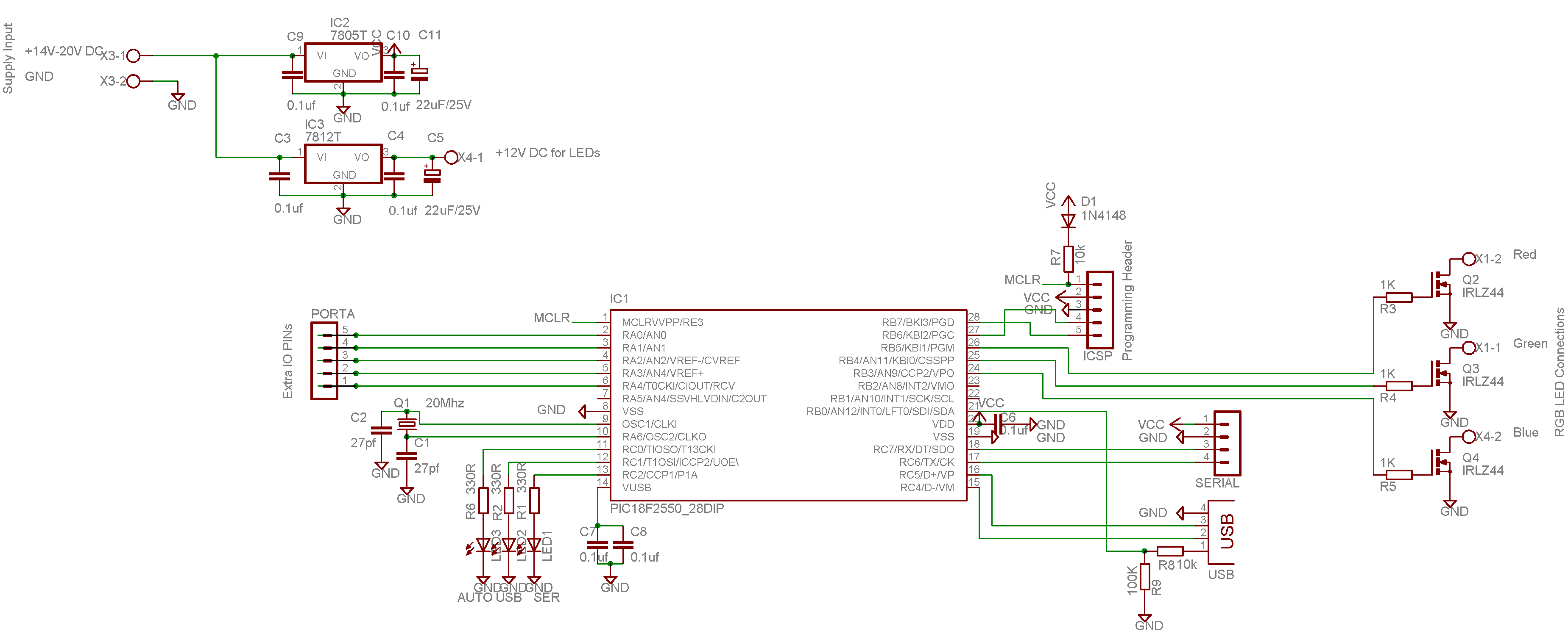
This color changer mixes light from high-power LEDs to create over 16 million colors. A smooth auto-fader cycles the colors, or it can be connected to a USB port for computer control. The device utilizes a well-known color model...
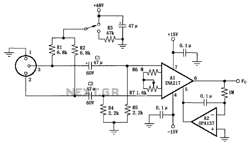
The circuit depicted in the figure consists of an INA217 professional miniature microphone preamplifier. A switch is included to select the use of phantom power. When the switch is connected to +48V, phantom power is enabled; if the switch...
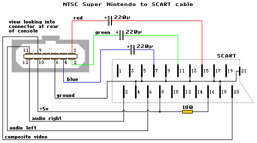
The schematic diagram is similar to the SNES NTSC RGB cable, with the only modification being the addition of capacitors to the RGB line. The diagram is accurate, but it does not include capacitors. A GameCube SCART lead can...