
DC/DC Power Supply Help
The design of a DC-DC power supply capable of outputting a regulated voltage between 12.7V and 14.5VDC from an input voltage that can start at 12VDC requires careful selection of components and configuration. This type of power supply is typically implemented using either a buck converter or a boost converter, depending on the specific requirements of the application and the input voltage range.
For a buck converter design, the circuit would include an input capacitor to stabilize the input voltage, an inductor to store energy, a switching element (usually a MOSFET), a diode for current flow direction, and an output capacitor to smooth the output voltage. The feedback control loop is essential for maintaining the desired output voltage; a voltage divider can be used to sense the output voltage and provide feedback to a PWM controller, which adjusts the duty cycle of the switching element to regulate the output.
In contrast, if the application requires a boost converter design—especially if the input voltage may be lower than the desired output voltage—similar components are used, but the configuration changes. The inductor is charged during the ON phase of the switch and releases energy to the output during the OFF phase, effectively stepping up the voltage.
In both designs, the choice of components such as the inductor value, capacitor ratings, and switching frequency will significantly affect efficiency and performance. Additionally, thermal management considerations must be addressed, as the switching elements can generate heat during operation. Proper heat sinking or thermal pads may be necessary to ensure reliable operation.
Overall, the schematic should include all necessary components, such as input and output capacitors, an inductor, a switching device, a diode, and a feedback loop with a PWM controller. The layout should minimize parasitic inductance and capacitance to enhance performance and reliability.Hi all, I am in need of a DC-DC Power supply schematic that outputs between 12.7 and 14.5VDC and an input that could be anywhere from 12VDC up to.. 🔗 External reference
Related Circuits
The following circuit illustrates the BUZ902DP 300 Watt Audio Power Amplifier Circuit Diagram. Features include audio frequency linearity from 20 Hz to 20 kHz. The BUZ902DP is a high-performance audio power amplifier designed to deliver up to 300 watts of...
This chapter presents detailed schematics for various power supplies compatible with commonly available Ar/Kr ion tubes in the surplus market. It includes examples of commercial designs such as the Omnichrome 150R and 532 head, Lexel 88 and head, alongside...
FET Q1 functions as a constant current generator, providing biasing for LED D1 and the base of Q2. This configuration ensures that D1 emits light at a consistent intensity, regardless of the battery voltage, which ranges from 3 to...
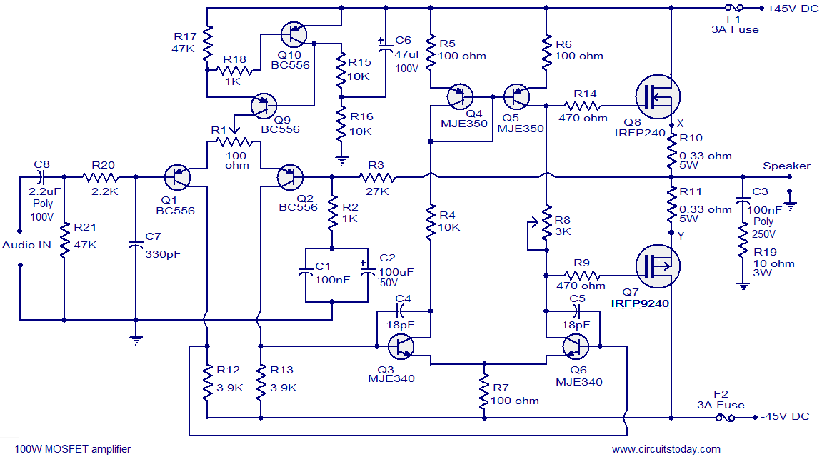
Hi-fi 100W MOSFET power amplifier circuit. Operates from a 45V dual supply. Delivers 100W to an 8-ohm speaker and 160W to a 4-ohm speaker, with low distortion. The Hi-fi 100W MOSFET power amplifier circuit is designed to provide high-quality audio...
Stabilized DC Power Supply with Short-Circuit Indication. The circuit provides four distinct regulated DC outputs (12V, 9V, 6V, and 5V) along with an unregulated 18V DC output, selectable via a rotary switch S2. The chosen output is displayed on...
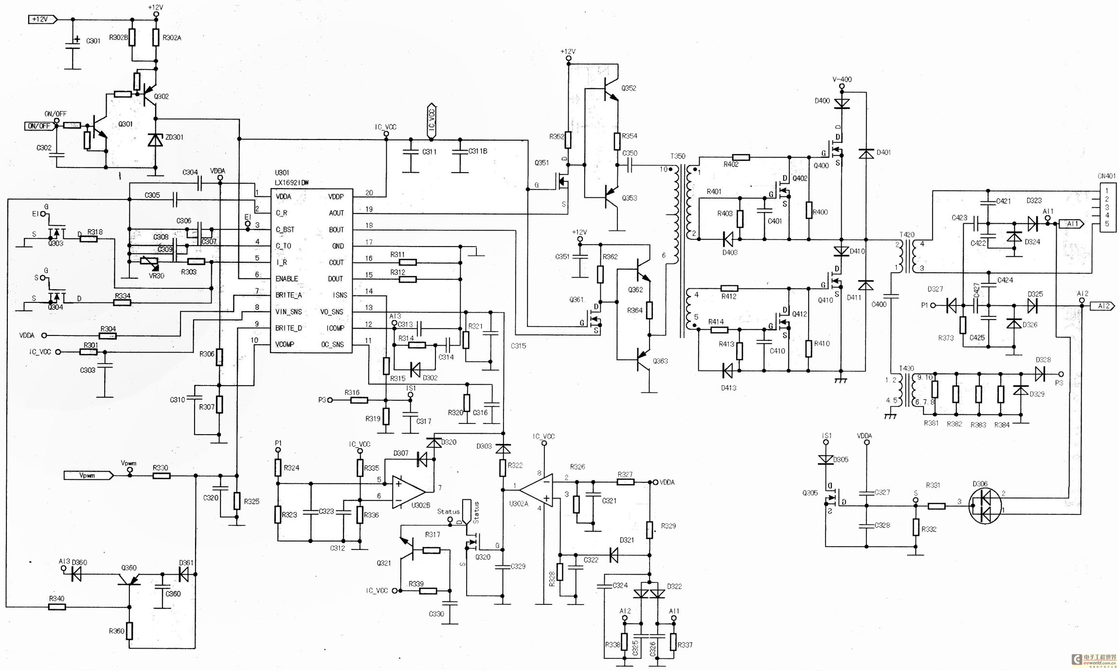
The main component is the LG26 one-inch screens integrated with the FSP107-2PS01 two-in-one electrical power package, which utilizes a direct drive CCFL modulator tube. This setup is compatible with screens from other manufacturers, such as Samsung and AU, but...