
Isolation transformer and low-pass filter wiring
The configuration of an isolation transformer and low-pass filter serves a critical role in electronic circuits, particularly in applications requiring noise reduction and signal integrity maintenance. The isolation transformer provides galvanic isolation, which helps to protect sensitive components from high voltage spikes and reduces the potential for ground loops.
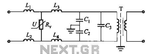
The low-pass filter, composed of multiple inductors (L1 to L4) and capacitors (C1, C2, and C3), is designed to allow low-frequency signals to pass while attenuating higher-frequency noise. The inductors are selected with values in the range of several to several tens of millihenries, which determines the cutoff frequency of the filter. The capacitors, with specified values ranging from 0.47 μF to 211 μF for C1 and C2, and 0.1 μF to 1 μF for C3, further define the filter's response characteristics.
Pressure-sensitive resistors are employed to ensure that the circuit can handle transient voltages without damage. These resistors are rated to manage currents of approximately 1.3 to 1.5 times the nominal voltage, providing an additional safety margin. The flow capacity rating of 1 to 3 kA indicates the maximum current the resistors can handle, which is crucial for applications that may experience high current surges.
In summary, this circuit design integrates an isolation transformer with a low-pass filter to enhance performance and reliability in electronic systems, ensuring effective noise suppression and protection of sensitive components.47. (3) isolation transformer and the low-pass filter junction isolation transformer and the wiring between the low-pass filter as shown in FIG. Figure (b) is a low-pass filter forms. Figure, Li ~ L4 take several to several tens of mH, Ci, C2 take 0.47 ~ 211F; C: i take Ol ~ lyF; R. The pressure-sensitive resistors take UlruA about 1.3-1.5 times the nominal voltage of the power supply of the rated voltage, flow capacity 1-3kA. Isolation transformer and low-pass filter wiring.
Related Circuits
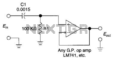
This simple 1 kHz filter utilizes a voltage follower and an RC section as its filtering element. For other frequencies, the -3 dB point is given by the formula 1/(6.28 Rl Cv), and the response decreases at a rate...
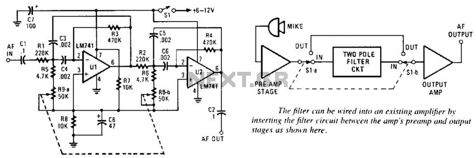
This variable-frequency audio bandpass filter is constructed using two 741 operational amplifiers (op amps) connected in cascade. Both op amps are configured as identical RC active filters, enhancing the selectivity of the overall circuit. The filter has a tuning...
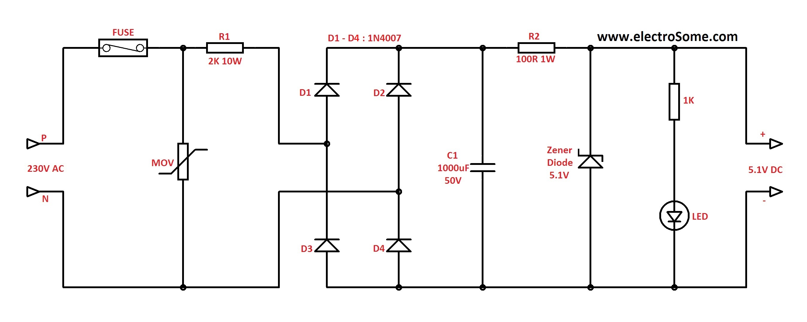
In Capacitor Power Supplies, a Voltage Dropping Capacitor is used in series with the phase line. Ordinary capacitors are unsuitable for these applications because mains spikes can create holes in the dielectric of standard capacitors, leading to failure. This...
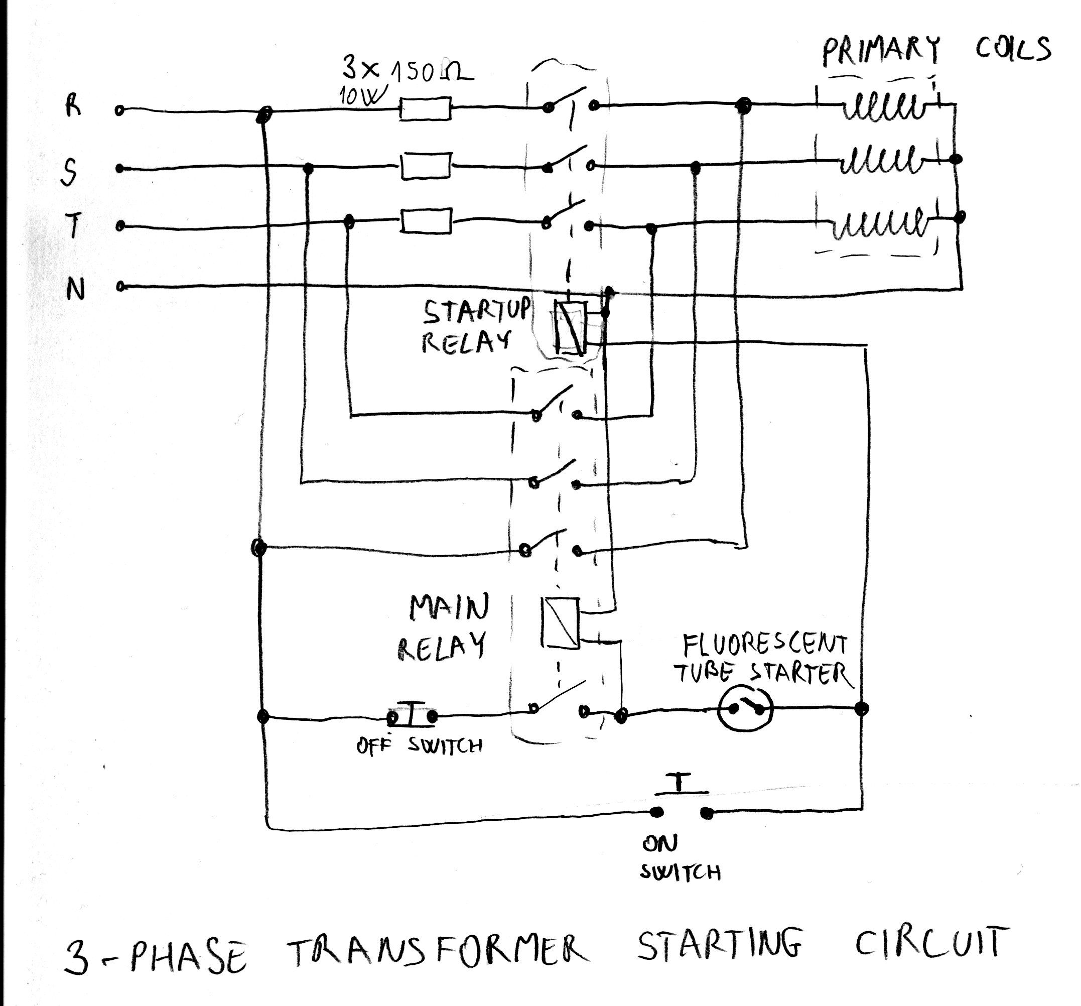
After acquiring a large 3-phase variable transformer (variac), there was an unexpected issue with it tripping circuit breakers at random when plugged in. Interestingly, the tripping occurred on different phases and seldom affected all three simultaneously. Resetting the breakers...
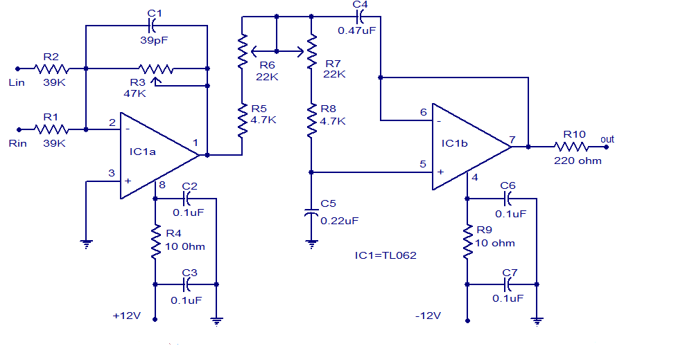
Several low-pass filter circuits for subwoofers are presented here, including this particular design. The circuit utilizes the TL062 operational amplifier from ST Microelectronics. The TL062 is a dual high-input impedance J-FET operational amplifier that features low power consumption and...
Mercury, Oldsmobile, Plymouth, Pontiac, muscle cars, and antique classic car wiring diagrams are continuously being added to this site. The wiring diagram for the Porsche 911L engine from the 1968 model has undergone changes since the original scheme. For...