
Variable-Frequency Audio Bp Filter Circuit
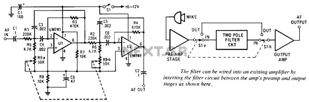
The described audio bandpass filter employs two 741 op amps, which are widely recognized for their versatility and reliability in analog signal processing. The cascading configuration of the op amps allows for the combination of their individual gains, resulting in improved selectivity and a more defined frequency response.
The RC active filter design utilizes resistors and capacitors to create a frequency-dependent response, where the cutoff frequencies are determined by the values of these components. In this case, the filter is tuned to pass signals within the range of 500 Hz to 1500 Hz, effectively attenuating frequencies outside this range. This characteristic makes it suitable for applications such as audio signal processing, where it is essential to isolate specific frequency bands.
The overall voltage gain of the filter being slightly greater than 1 indicates that the output signal is amplified, but not excessively, which is beneficial for maintaining signal integrity. The gain of approximately 5 for the filter itself suggests that it is designed to enhance the amplitude of the desired frequency components significantly.
Input handling capabilities of up to 4 V peak-to-peak demonstrate the circuit's robustness, ensuring that it can process typical audio signals without distortion or clipping. The high input impedance of over 200 kΩ minimizes the loading effect on preceding stages, allowing for better signal fidelity. Conversely, the low output impedance of less than 1 kΩ facilitates easy interfacing with subsequent stages of an audio system, ensuring efficient signal transfer.
In summary, this variable-frequency audio bandpass filter utilizing 741 op amps is a well-designed circuit for selective frequency amplification, suitable for various audio applications where precise control over frequency response is required. This variable-frequency, audio bandpass filter is built around two 741 op amps that are connected in cascade. Two 741 op amps are configured as identical RC active filters and are connected in cascade for better selectivity.
The filter`s tuning range is from 500~Hz to 1500 Hz. The overall voltage gain is slightly greater than 1 and the filter`s is about 5, The circuit can handle input signals of 4 V peak-to-peak without being overdriven. The circuit`s input impedance is over 200 kohm. and its output impedance is less than 1 kohm. 🔗 External reference
Related Circuits

The hardware design for USB is quite minimal, which is advantageous. However, it quickly becomes apparent that the simplicity of the hardware design leads to complex communication and control software, which will be explored further in the theory and...
This circuit should only be attempted by individuals with a strong understanding of electronic devices. It is connected to a main power source (220V) and poses a risk of high electrical shock. This circuit operates at a mains voltage of...
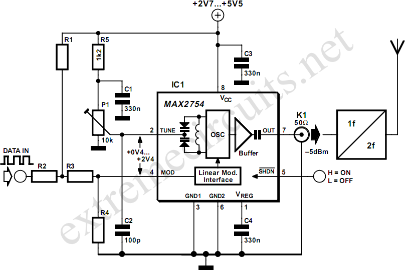
High-frequency voltage-controlled oscillators (VCOs) are challenging to construct, which is why Maxim has developed the integrated 1.2 GHz oscillator, the MAX2754. The center frequency is adjustable via the TUNE input, while a linear modulation input allows for frequency modulation....
The working principle involves two pairs of photoelectric detection devices installed in the access channel. One side features light source A (transmitter) and photoresistor LDR1 (receiver) at the entrance of the channel, while the other side contains light source...
The following circuit illustrates a Mains Remote-Alert Circuit Diagram. Features include simple circuitry, with the transmitted signal being conveyed effectively. The Mains Remote-Alert Circuit is designed to provide a notification system that alerts users about the status of mains power....
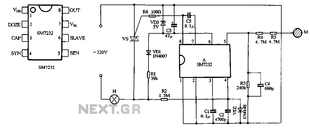
The core component of the circuit is the dimmer, utilizing the SM7232 integrated circuit. The pin configuration includes: 1) VDD, the positive power supply terminal; 2) DOZE; 3) CAP; 4) SYN, which synchronizes input power frequency using an internal...