
JDM pic programmer help required
The JDM PIC microcontroller programmer is a widely used circuit for programming PIC microcontrollers via the RS232 interface. The RS232 communication standard utilizes a set of pins on the PIC microcontroller for receiving serial data. Typically, the relevant pins on the PIC microcontroller include the RX (Receive) pin and potentially other signal lines depending on the specific implementation of the circuit.
In a standard configuration, the RX pin is responsible for receiving the incoming data from the RS232 interface. The signal levels of RS232 are typically inverted compared to TTL logic levels, meaning that a logic high is represented by a negative voltage, and a logic low is represented by a positive voltage. To interface the RS232 signals with the PIC microcontroller, a level-shifting component, such as a MAX232 or a similar RS232 to TTL converter, is often employed. This component converts the RS232 voltage levels to TTL levels that the PIC can interpret correctly.
In addition to the RX pin, the circuit may also utilize the TX (Transmit) pin, which sends data from the PIC microcontroller back to the RS232 interface. Other control signals, such as RTS (Request to Send) and CTS (Clear to Send), may also be involved depending on the complexity of the communication protocol being used.
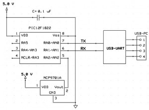
When designing or analyzing the JDM programmer circuit, it is crucial to consult the specific datasheet for the PIC microcontroller in use, as pin assignments and functionalities may vary between different models. Proper attention to the connection and configuration of these pins ensures reliable communication between the PIC microcontroller and the programming interface.For the following circuit of the JDM pic microcontroller programmer I need information about the PIC microcontroller pins which receive the RS232.. 🔗 External reference
Related Circuits

This application note discusses the use of SEPIC power modules to supply the necessary power for driving high-brightness LED arrays. These arrays serve as display backlights and necessitate a wide dimming range. The SEPIC configuration offers an efficient and...
The Atmel Flash devices are ideal for developing, since they can be reprogrammed easy and fast. If you need more code space for your application, particularly for developing 89Cxx projects with C language. Atmel offers a broad range of...
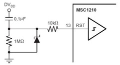
A flash memory schematic can be created using various reset sources, including power-on reset, external reset, software reset, watchdog timer reset, and brownout reset. The accompanying figure illustrates a recommended external reset circuit for the MSC1210, which includes a...

The following circuit illustrates a stepper motor controller. This circuit is based on the PIC16F84A integrated circuit. Features: a transistor is utilized to drive the motor. The stepper motor controller circuit employs the PIC16F84A microcontroller, which serves as the central...
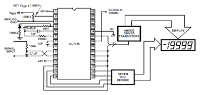
The ICL7135 typical application schematic diagram is illustrated in the following circuit. This Analog to Digital (A/D) converter incorporates all necessary active devices on a single CMOS integrated circuit, featuring multiplexed BCD output and digit drivers. The ICL7135 is a...
This project outlines a simple and cost-effective method for integrating a digital thermometer and data logging capability into a PC. It utilizes a PIC microcontroller to obtain temperature data from the Microchip MCP9701 sensor and transmits this information to...
Warning: include(partials/cookie-banner.php): Failed to open stream: Permission denied in /var/www/html/nextgr/view-circuit.php on line 713
Warning: include(): Failed opening 'partials/cookie-banner.php' for inclusion (include_path='.:/usr/share/php') in /var/www/html/nextgr/view-circuit.php on line 713