
Stepper motor controller Based On The PIC16F84A IC
The stepper motor controller circuit employs the PIC16F84A microcontroller, which serves as the central processing unit for controlling the stepper motor's operation. The PIC16F84A is an 8-bit microcontroller with a 14-bit instruction set architecture, allowing for efficient control algorithms to be implemented.
The circuit typically includes a driver stage, which often consists of one or more transistors. These transistors are crucial as they amplify the control signals from the microcontroller to provide sufficient current to the stepper motor coils. The choice of transistor is important; commonly used transistors include N-channel MOSFETs or bipolar junction transistors (BJTs), depending on the current requirements of the motor.
The control logic for the stepper motor can be implemented in various modes, such as full-step, half-step, or microstepping, which can be programmed into the PIC16F84A. The microcontroller generates the necessary pulse sequences to energize the motor coils in the correct order, resulting in precise control of the motor's rotation.
Additional components in the circuit may include resistors, capacitors, and diodes. Resistors may be used for current limiting, while capacitors can help stabilize the power supply and filter out noise. Diodes are often included to protect the circuit from back EMF generated by the motor when it is turned off, ensuring the longevity of the components.
The power supply for the circuit should be chosen based on the voltage and current specifications of the stepper motor, ensuring that it meets the operational requirements without exceeding the ratings of the microcontroller and driver components. Proper layout and grounding techniques should also be employed to minimize electromagnetic interference and ensure reliable operation of the stepper motor controller.The following circuit shows about Stepper motor controller. This circuit based on the PIC16F84A IC. Features: transistor is used to drive the .. 🔗 External reference
Related Circuits
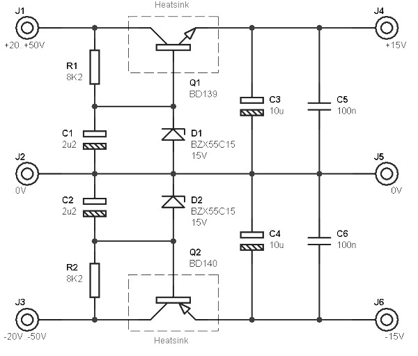
This circuit is designed to be integrated into an existing circuit, such as an audio amplifier, which already supplies symmetric voltages of +20V/-20V and +50V/-50V. The schematic diagram is derived from a dual polarity power supply circuit providing +/-...

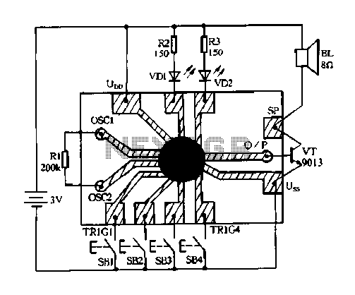
The construction and operation of brushless motor windings are based on the principle of triangular coils. Through the switch, the stator coil current can be cycled, resulting in the formation of a rotating magnetic field. The cycle of the...
Constantly changing light and sound analog controller circuit 04 The circuit designated as the "Constantly Changing Light and Sound Analog Controller Circuit 04" is designed to modulate both light and sound outputs in a dynamic manner. This type of...
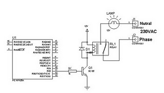
A relay can be controlled using a PIC microcontroller. The circuit illustrates how to control a single relay with the PIC 16F628. When the RB5 port of the PIC is set to high, the relay will activate. This circuit...
The 0.1µF monolithic capacitors will be marked '103 K' and the 15pF monolithic capacitors are marked '15 J'. It is crucial not to confuse the two. Do not remove either the MOSFETs or the integrated circuits from their protective...
The principles of DC motors are discussed in the beginner and intermediate sections of this tutorial. This section will address the electronics required to interface them with a Basic X microcontroller or other digital chips. The simplest method of...
Warning: include(partials/cookie-banner.php): Failed to open stream: Permission denied in /var/www/html/nextgr/view-circuit.php on line 713
Warning: include(): Failed opening 'partials/cookie-banner.php' for inclusion (include_path='.:/usr/share/php') in /var/www/html/nextgr/view-circuit.php on line 713