
JFET static detector
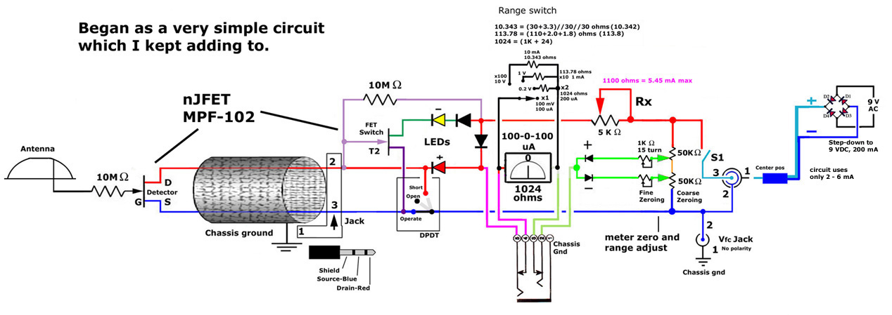
The JFET (Junction Field Effect Transistor) static charge detector operates by utilizing the unique characteristics of JFETs to sense variations in electric fields. The basic configuration typically includes a JFET connected in a common-source or common-drain arrangement, which allows for high input impedance and sensitivity to static charges.
In the design, the gate of the JFET is exposed to the environment, enabling it to detect electric fields generated by static charges. The output can be monitored through a load resistor connected to the drain, where the voltage variations reflect the presence of static charge. It is crucial to ensure proper biasing of the JFET to keep it in the active region, thus maintaining its sensitivity.
The differences observed in various versions of the static charge detectors could stem from several factors, including variations in JFET specifications, differences in the circuit layout, or the use of different materials for the gate. Additionally, environmental factors such as humidity and temperature can influence the performance of these detectors.
To enhance the performance of the static charge detector, it is advisable to implement a shielding mechanism to minimize interference from external electric fields. Furthermore, incorporating a feedback mechanism could stabilize the output and improve the accuracy of the readings.
Overall, JFET static charge detectors serve as valuable tools in applications requiring the detection of static electricity, and understanding the nuances of their design and operation is essential for optimizing their performance.Hello, this is my first post here. I built several versions of JFET static charge detectors and I`m seeing some differences I can`t explain so I`m.. 🔗 External reference
Related Circuits
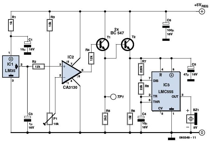
This is an Overheat Detector Alarm Switch using the Temperature Sensor IC LM35. The core of this overheat detector (fire alarm) circuit is a precision integrated temperature sensor, the LM35 (IC1), which provides an accurately linear and directly proportional...
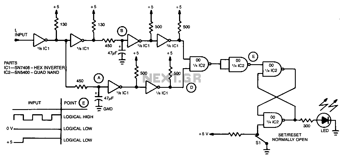
A simple inverter and NAND gate can be connected to create a highly compact and reliable digital frequency detector. This circuit is capable of detecting frequencies up to 3 MHz with a 50% duty cycle. When a frequency appears...
The metal detector circuit is shown here that the limits represent the sake of simplicity for a metal detector, but the design works remarkably well. It only uses 40,106 Hex Schmitt inverter IC, a capacitor and a search coil...
The project demonstration has been successfully completed, with the only remaining task being the final project report due on June 15, which will be integrated with a conference paper. This update marks the last entry in the electronic notebook,...
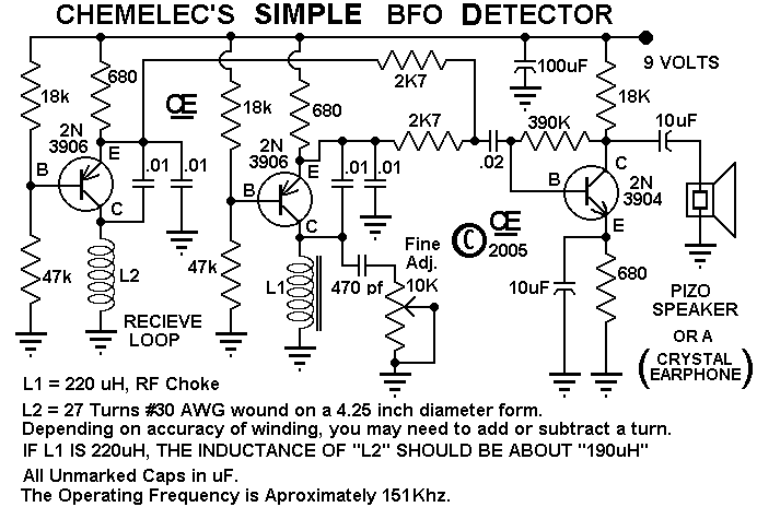
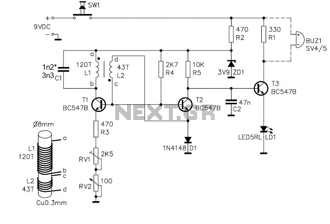
A Very Simple "Beat Frequency Oscillator" type of Metal Detector. These are about the Simplest of all Metal Detector types, But still quite useful for many Detecting applications. And although this one is particularly simple, it works very well. The...
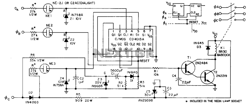
This circuit derives its supply voltage, Vcc, and Vdd from the AC supply. This factor, along with the neon lamps and zener diodes in the phase inputs, establishes a 50% threshold that detects low voltage or the absence of...