
Joule thief AA battery led circuit

The Joule Thief circuit is a simple and efficient boost converter designed to extract usable energy from a low-voltage source, such as a nearly depleted AA battery. The essential components of this circuit include a transistor (typically a NPN type), a resistor, an inductor, and a light-emitting diode (LED).
In the schematic, the power source (V1) represents the AA battery with a voltage of approximately 1 volt. This low voltage is insufficient to power most LEDs directly; however, the Joule Thief circuit utilizes the principles of inductive energy storage and oscillation to increase the voltage. The transistor acts as a switch that rapidly turns on and off, allowing current to flow through the inductor. When the transistor is on, the inductor stores energy in its magnetic field. When the transistor turns off, the magnetic field collapses, inducing a higher voltage across the inductor, which can then forward-bias the LED, allowing it to light up.
The resistor in the circuit is crucial as it limits the base current flowing into the transistor, ensuring that it operates within its safe limits. The LED serves as the load, providing visual feedback that the circuit is functioning. The efficiency of the Joule Thief circuit allows it to illuminate an LED even when the battery voltage is too low for direct use, making it an excellent solution for maximizing the lifespan of batteries that would otherwise be discarded.
Overall, the Joule Thief circuit is an innovative approach to energy conservation, demonstrating how simple electronic components can be utilized to harness energy from sources that are typically considered depleted.4 thoughts on Joule thief AA battery led circuit. In the schematic of the led circuit you can see the power source (V1) that represents an empty battery. It has only 1 volts remaining and an internal. 🔗 External reference
Related Circuits
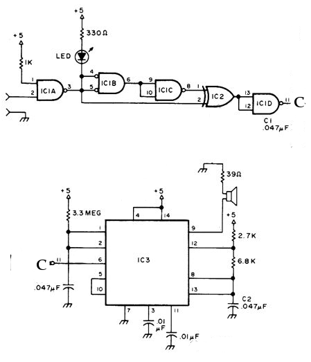
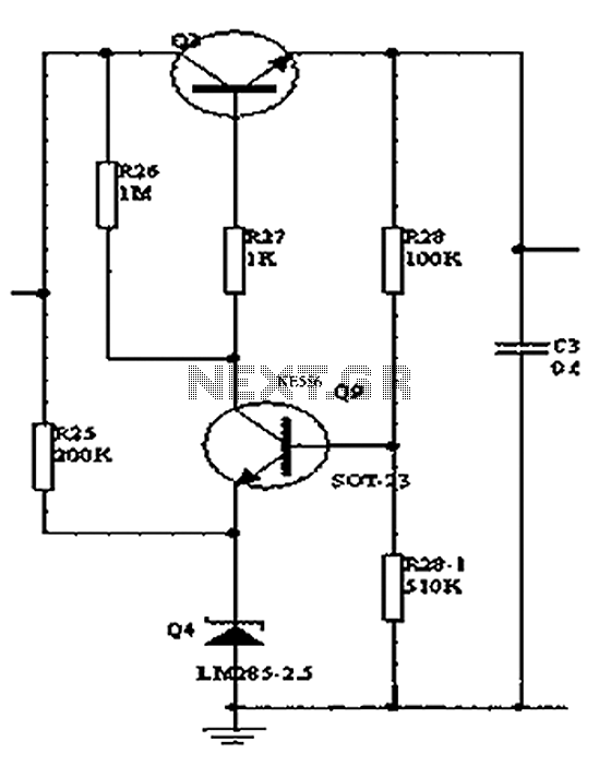
The NE556 timer can function as an indicator for the static state of a digital logic audible terminal. An audible logic probe is beneficial for visually inspecting a component while simultaneously checking the logic state at another point far...
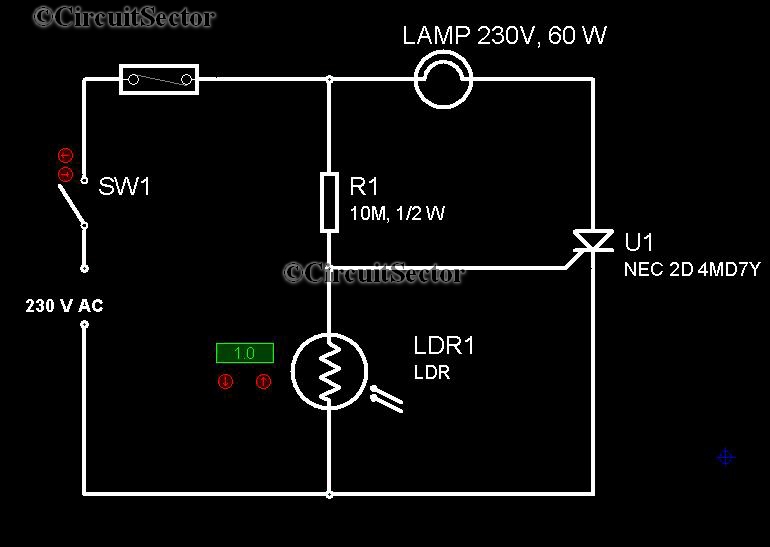
It is very convenient to automatically light a lamp in our absence during the evening when it gets dark. This automatic night lamp circuit can be utilized to illuminate staircase lights, porch lights, etc., automatically using a domestic power...
Modern acid batteries and lead plates are embodiments of simplicity in use. Unlike NiCd batteries, they must be recharged by connecting to a constant voltage source. Modern acid batteries, commonly referred to as lead-acid batteries, consist of lead plates submerged...
Designs for audio amplifiers with DC coupling to the load are not frequently seen today, despite offering distinct advantages. Audio amplifiers that employ DC coupling to the load provide several benefits that can enhance performance in specific applications. In traditional...
The program utilizes the Linear LT1934 chip for the production of a high-efficiency power supply circuit design that is less demanding in terms of electrical load. It offers considerable adjustment margins. When supplied with a 24VDC input, the non-isolated...
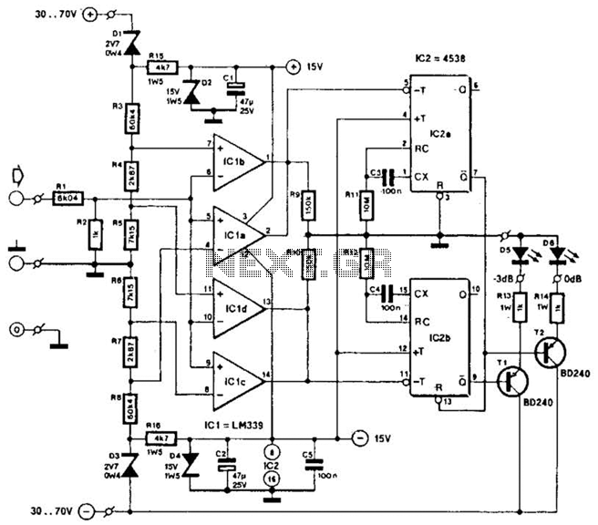
This circuit was utilized with an audio power amplifier to identify the point at which the output is -3 dB from maximum, indicated by LED D5, and at clipping, shown by LED D6. The indicator can be employed with...