
Joule Thief Circuit Experiment
The circuit described utilizes a 555 timer IC, which is a versatile component commonly used for generating precise timing and oscillation signals. In this configuration, the timer can operate in astable mode, producing a continuous square wave output. The optional components, R1, D3, and C1, can enhance the circuit's functionality but are not strictly necessary for its basic operation.
The LED serves as a visual indicator of the circuit's operation. If the LED fails to light, the polarity must be checked, as LEDs are polarized devices that require correct orientation for proper function.
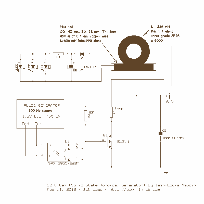
The mention of high current consumption in the original setup suggests that the circuit may need optimization to reduce power usage. The R5 resistor, which is likely part of the timing components or load for the BUZ 11 transistor, is noted for overheating at a frequency of around 200 Hz. This indicates that the resistor may be undersized for the application or that the current flowing through it is too high, necessitating a review of the resistor's value and power rating.
The BUZ 11 is a power transistor that can handle higher currents and is often used in switching applications. Its overheating suggests that it is operating near its limits, which can lead to reliability issues. The use of a frequency generator instead of a single 555 timer allows for more precise control over the output frequency and duty cycle, which is beneficial for applications requiring specific timing characteristics.
In summary, the circuit design involves a basic LED indicator, a 555 timer for oscillation, and a BUZ 11 transistor for switching, with considerations for component selection and thermal management to ensure reliable operation. Further analysis of the circuit parameters and adjustments to component values may be necessary to improve performance and efficiency.R1, D3 and C1 are optional! You just need one LED. If it does not work, try to switch the LED polarity. I first tried a single 555 CCT (CirCuiT). I was annoyed by the huge current consumption. The R5 resistor and the BUZ 11 did get very hot at about 200 HZ. So, as the feq and Duty Cycle (DTC) is not easy to tune with a single 555, I decided to use a Freq Gen. 🔗 External reference
Related Circuits
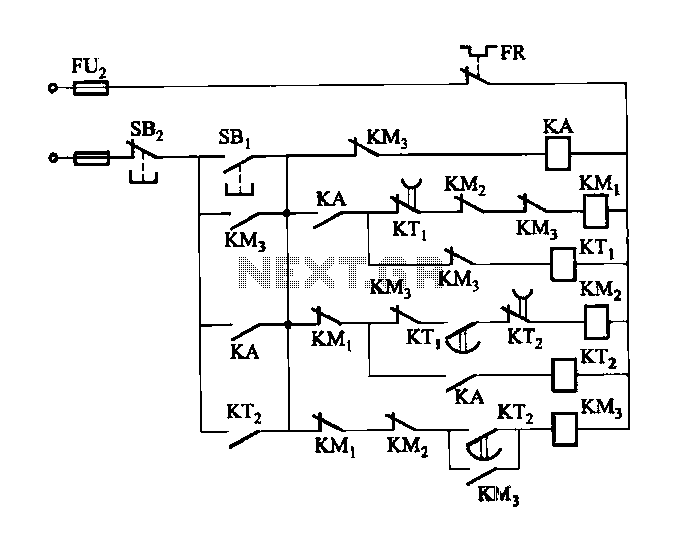
Figure 3-118 illustrates an automatic acceleration control circuit. This circuit employs a male contactor time relay, enabling the motor to start automatically at a low speed before transitioning to high-speed operation. The automatic acceleration control circuit depicted in Figure 3-118...
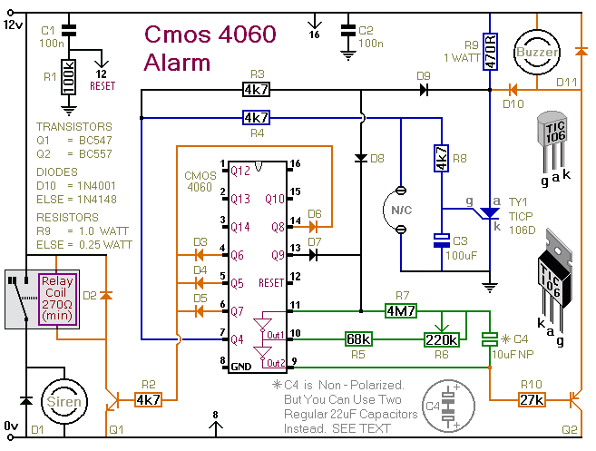
This is a single-zone alarm system featuring automatic exit, entry, and siren cut-off timers. It is designed to accommodate various types of normally-closed input devices, including magnetic reed contacts, foil tape, and passive infrared sensors (PIRs). Additionally, it is...

This design circuit is for an electrostatic transducer used in ultrasonic measurement applications. It employs the LM1812 ultrasonic transceiver. The transducer (X1) and the LM1812 work together to transmit a burst of oscillations. The return echo is detected by...
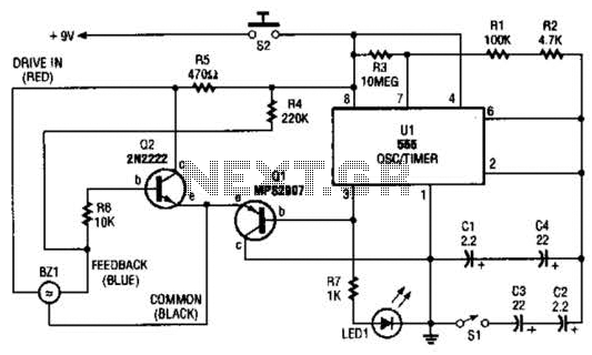
The electronic darkroom timer is constructed using a 555 oscillator/timer, a pair of general-purpose transistors, a buzzer, and an LED. The 555 timer (U1) is set up as an astable multivibrator, functioning as a free-running oscillator. The frequency of...
The objective of this project was to design a small portable mixer powered by a 9V PP3 battery while maintaining performance quality. The mixer consists of three main modules that can be varied in number and can be adapted...
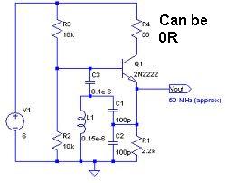
An oscillator circuit capable of generating a high-quality sine wave with a frequency of at least 500 MHz, intended for RFID applications. There have been attempts to utilize a class E oscillator, but the design has not yet been...
Warning: include(partials/cookie-banner.php): Failed to open stream: Permission denied in /var/www/html/nextgr/view-circuit.php on line 713
Warning: include(): Failed opening 'partials/cookie-banner.php' for inclusion (include_path='.:/usr/share/php') in /var/www/html/nextgr/view-circuit.php on line 713