
2 -Y- connection automatic three-speed motor acceleration control circuit
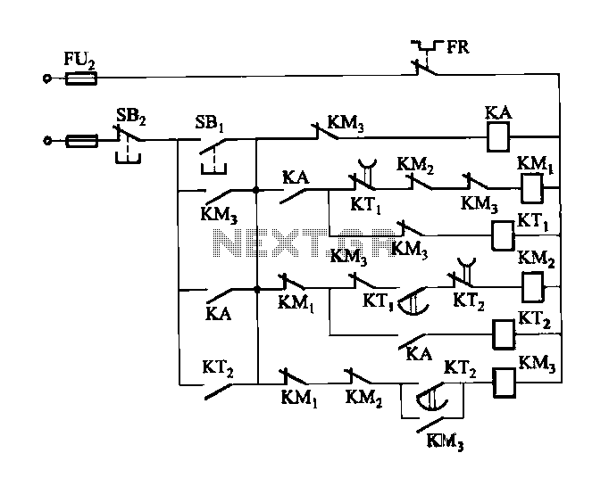
The automatic acceleration control circuit depicted in Figure 3-118 is designed to enhance motor performance by providing a controlled ramp-up in speed. The primary component, a male contactor time relay, plays a crucial role in managing the motor's startup sequence. Upon activation, the time relay initiates the motor at a predetermined low speed, allowing for a gradual increase in speed to high operational levels.
The circuit typically consists of the following components: a power supply, the male contactor time relay, a motor, and various control elements such as switches and resistors. The power supply provides the necessary voltage and current to the motor and relay. The male contactor time relay is configured to close its contacts after a specific delay, which is adjustable based on the application requirements. This delay ensures that the motor does not start at full speed immediately, thus preventing mechanical stress and potential damage.
In operation, when the circuit is powered, the relay remains open for a set duration, during which the motor operates at low speed. After the elapsed time, the relay closes, allowing the motor to transition smoothly to high-speed operation. This method not only improves the reliability and longevity of the motor but also enhances overall system efficiency.
In addition to the relay, the circuit may incorporate safety features such as overload protection and thermal sensors to monitor motor temperature. These elements ensure that the motor operates within safe parameters, further contributing to its durability and performance. The design can be tailored to various motor types and applications, making it a versatile solution for automatic acceleration control in industrial and commercial settings.Figure 3-118 automatic acceleration control circuit. It uses the male contactor time relay, the motor starts automatically from a low speed by the speed the transition to high- speed operation.
Related Circuits
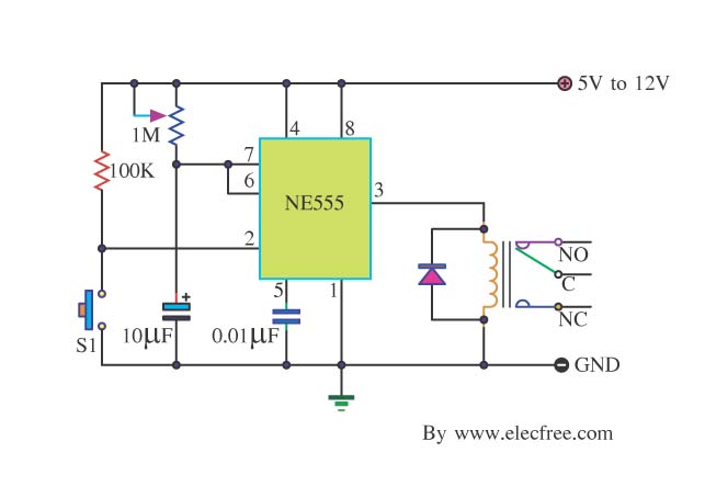
Many friends take an interest in the circuit involving the highly popular IC 555, which is an integrated circuit. This circuit sets the time in a basic manner. The IC 555 timer is a versatile and widely utilized component in...
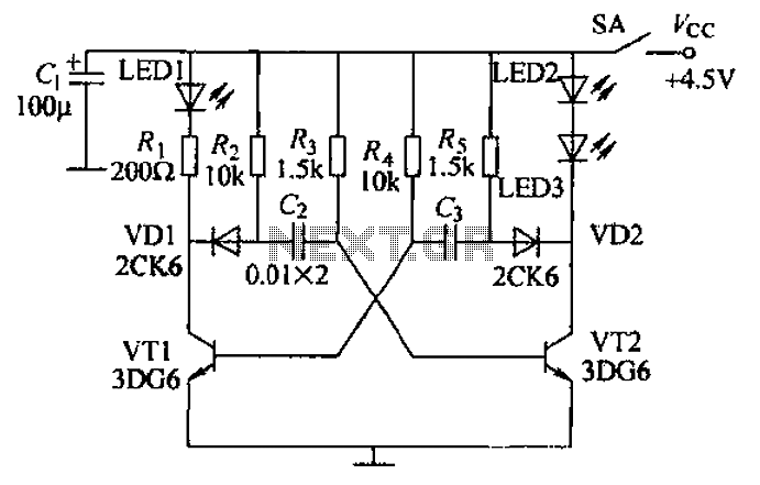
Transistors VT1, VT2, and associated RC components are configured to form a multivibrator. The multivibrator operates with resistors Ra and R4 serving as base bias resistors for VT2 and VT1, respectively. When the switch SA is closed after applying...
This portable solar lantern circuit utilizes a 6 volt/5 watt solar panel, which is widely available. With this photovoltaic panel, an economical, simple, yet efficient and truly portable solar lantern unit can be constructed. The next essential component required...
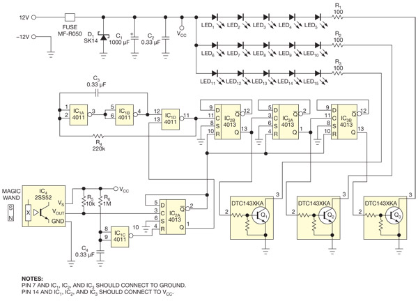
This circuit enables the activation of holiday bulbs with a wave of a magic wand. The strings of lights flash in a sequential manner. The core concept relies on a magnet. The circuit operates by utilizing a magnet as the...
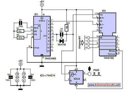
PWM waveforms are frequently utilized to regulate the speed of DC motors. The duty cycle of the digital waveform can be defined using an adjustable parameter. PWM (Pulse Width Modulation) is a technique employed to control the power delivered to...
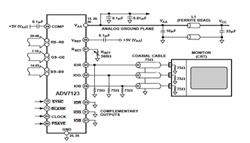
This digital-to-analog converter (DAC) integrated circuit is designed for optimal noise performance, minimizing both radiated and conducted noise. A recommended connection diagram for the ADV7123 is depicted in the following schematic diagram. According to the ADV7123 datasheet, this device...
Warning: include(partials/cookie-banner.php): Failed to open stream: Permission denied in /var/www/html/nextgr/view-circuit.php on line 713
Warning: include(): Failed opening 'partials/cookie-banner.php' for inclusion (include_path='.:/usr/share/php') in /var/www/html/nextgr/view-circuit.php on line 713