
rfid How to design an Oscillator Circuit (500 MHz range) with no Op amps
The oscillator circuit for RFID applications requires careful consideration of various design parameters to ensure it functions effectively at high frequencies. A class E oscillator is a popular choice for generating high-frequency signals due to its efficiency and simplicity, but it necessitates precise component selection and configuration.
To create a reliable 500 MHz sine wave, the following components and considerations are essential:
1. **Transistor Selection**: A high-frequency transistor, such as a FET or a BJT rated for RF applications, should be chosen. The transistor must support the necessary frequency and provide sufficient gain.
2. **Resonant Tank Circuit**: The core of the oscillator is the resonant tank circuit, typically consisting of an inductor (L) and a capacitor (C). The values of these components must be calculated to resonate at the desired frequency. The resonant frequency \( f \) can be calculated using the formula:
\[
f = \frac{1}{2\pi\sqrt{LC}}
\]
Proper tuning of L and C is crucial to achieving the target frequency.
3. **Feedback Network**: A feedback network is required to sustain oscillation. This can be achieved through a combination of resistors and capacitors that ensure the correct phase shift and gain for oscillation.
4. **Power Supply**: The circuit must have a stable power supply to maintain consistent operation. Voltage regulation may be necessary to avoid fluctuations that could affect the output frequency.
5. **Output Filtering**: To obtain a clean sine wave, output filtering may be implemented. This can involve additional LC filters that remove harmonic content and ensure the output is suitable for RFID applications.
6. **PCB Design**: At high frequencies, the layout of the printed circuit board (PCB) becomes critical. Short traces, proper grounding, and minimized parasitic capacitance and inductance are essential to maintain signal integrity.
7. **Testing and Tuning**: After assembly, the circuit should be tested with an oscilloscope to verify the output waveform. Adjustments may be necessary to fine-tune the component values and ensure the oscillator operates at the desired frequency with minimal distortion.
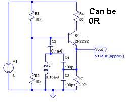
By addressing these components and considerations, a functional class E oscillator capable of generating a 500 MHz sine wave for RFID applications can be successfully designed and implemented.An Oscillator circuit which can produce a good sine wave with a frequency of at least 500 Mhz. This is for RFID applications. I have tried to use an class E oscillator, but i cant seem to get the design right. Can anyone help me out 🔗 External reference
Related Circuits
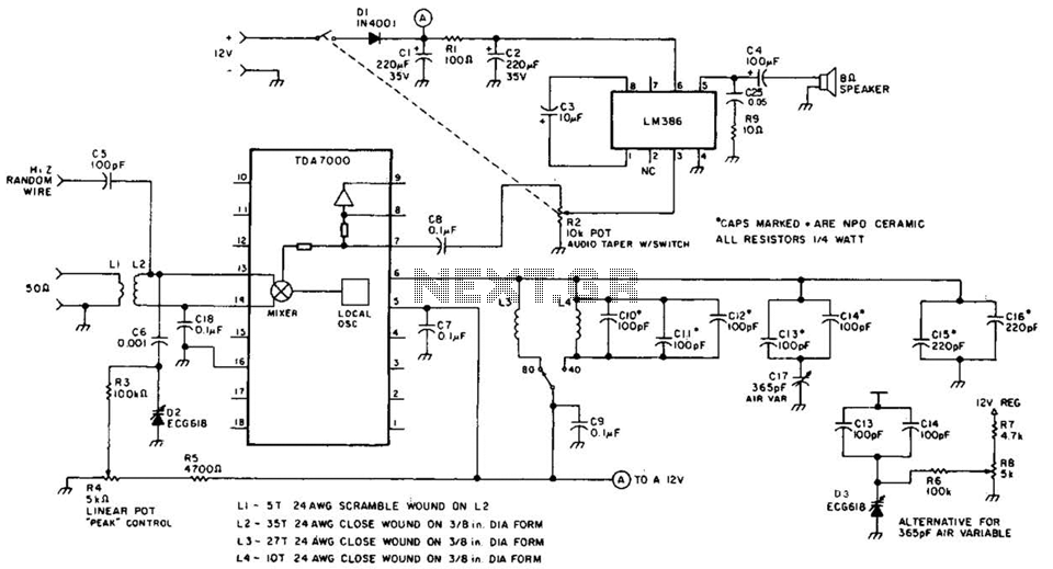
This direct-conversion receiver utilizes a TDA7000 integrated circuit (IC) and incorporates an LM386 audio amplifier. The TDA7000 serves as the mixer and local oscillator (L.O.) section. The frequency control can be achieved using either an air variable capacitor or...
This small circuit transmitter processes audio signals from a sound table or microphone, as well as video signals from a camera, DVD, or video cassette. It has a composite video output, allowing direct transmission from a computer over a...
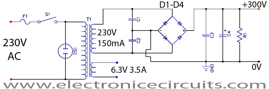
This project is a successful vacuum tube amplifier utilizing a 6V6GT output pentode configured in triode mode, producing approximately 4.5 watts of output power. The design features a single-ended audio amplifier with a resistive input network, a driver stage,...
Half of a Motorola MG14538B dual precision retriggerable monostable multivibrator is utilized to create an extended on-time timer circuit. This type of circuit can function as a switch debouncer. Such circuits are commonly implemented in digital applications, where every...

This circuit is a conventional Pierce type oscillator that utilizes a JFET. It employs fundamental mode crystals and demonstrates good performance and reliability when a low noise JFET is used. The feedback is regulated by the capacitance C1, which...
A unijunction transistor (UJT) is an electronic semiconductor device characterized by a single junction. It consists of three terminals: an emitter (E) and two bases (B1 and B2). The base is constructed from a lightly doped n-type silicon bar,...
Warning: include(partials/cookie-banner.php): Failed to open stream: Permission denied in /var/www/html/nextgr/view-circuit.php on line 713
Warning: include(): Failed opening 'partials/cookie-banner.php' for inclusion (include_path='.:/usr/share/php') in /var/www/html/nextgr/view-circuit.php on line 713