
Kapanadze 2
Warning: Undefined array key "extension" in /var/www/html/nextgr/view-circuit.php on line 468
Deprecated: strtolower(): Passing null to parameter #1 ($string) of type string is deprecated in /var/www/html/nextgr/view-circuit.php on line 468

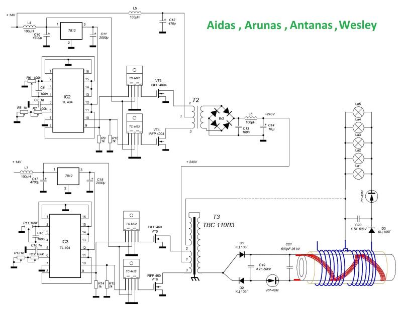
The described DC/DC converter is designed to step down voltage from standard mains supply levels (110V or 220V) to a lower voltage of 12V. This converter is particularly useful in applications where a stable 12V supply is needed, such as in battery replacement scenarios. The configuration utilizes a transformer with four windings, which allows for the necessary voltage transformation and isolation. The mention of L4 indicates a specific inductor or coil that plays a role in energy storage or filtering within the circuit.
The pulse generators operating at 5V are likely responsible for driving the switching transistors that control the power delivery to the load. The nanopulser component is critical in ensuring that the output is stable and does not produce erratic pulses, which could lead to inefficiencies or damage to connected devices. The synchronization of the nanopulser with the inverter's phase is essential for maintaining consistent performance.
The G202 diode's role as a spark gap equivalent suggests that it is used for voltage clamping or protection, which is important in high-voltage applications to prevent damage from voltage spikes. The functionality of transistor Q3, which inverts the output of the NAND gates in integrated circuit U3, indicates that logic level manipulation is part of the control mechanism for the converter.
Assembly of the circuit is straightforward, but attention to detail is crucial. The specified correction regarding the IRF460 transistor gate connection highlights the importance of proper circuit design and component interaction to ensure reliable operation. Any misconnection could lead to malfunction or failure of the converter, emphasizing the need for careful adherence to the schematic and design specifications.the dc/dc converter is 110/220->12v not the other way. so the 12V takes the place of the battery, this comes from L4 (what you have marked L3) on t1 there`s really 4 windings, the 4th goes to the top GEN2 (you have 2 gen2`s) The pulse generators are running on 5V, the power transistors in nanopulser are switching 150V, another 150V from same inver ter transformer goes into output coil. The nanopulser is locked into inverter`s phase so it does not spit out random pulses. Also G G 202 diode there is doing same function as spark gap in Tesla coil. According to the attached schematic (which is identical to your but translated to english), the transistor Q3 will invert the output of the NAND Gates in Integrated Circuit U3. Its very easy to assemble system 1:1, sure need correct some mistakes (for ex. not connect gate of IRF460 with 3100pF input cap. directly to TL494 outputs). But in result for sure nothing will work. 🔗 External reference
Related Circuits
A circuit diagram has been found on a Russian website, freeenergylt.narod2.ru/Aidas. The diagram includes a pulse generator, which requires PCGU1000 equipment for the coils to function. There are discussions about the internal resonation design, involving a capacitor in parallel...

If the scope probes are not isolated, it is still possible to connect the grounding leads of the probes to point A while connecting the tips of the probes to points B and C. The resulting current traces will...

The emitter voltage drops completely to 0V from 42V during the pulse when the transistor is conducting or saturated. This contrasts with a pure resistive load (the 4.7 Ohm resistor mentioned in the previous video), where the collector-emitter voltage...
The 22-turn coil is positioned above the 84-turn coil. Connecting this coil significantly impacts performance. Testing with a 1 kW heater yielded better results; however, prolonged use may lead to failure. The heater's wire typically does not glow as...
The device features high-voltage (HV) insulation made of polystyrene. Incorporating ferrite may serve as a method to lower the frequency. However, using copper could lead to short circuits due to its interaction with radiant energy. It is noted that...
If the same procedure is performed after W2, the maximum voltage will be achieved. The released S1 on W2, shortly after a short circuit, will generate Back Electromotive Force (BEMF) in W2, which is usually 20-30 times higher than...