
Kapanadze 5
Warning: Undefined array key "extension" in /var/www/html/nextgr/view-circuit.php on line 468
Deprecated: strtolower(): Passing null to parameter #1 ($string) of type string is deprecated in /var/www/html/nextgr/view-circuit.php on line 468

In this circuit analysis, the behavior of the transistor under different load conditions is examined. The emitter voltage's complete drop to 0V during saturation indicates effective transistor operation, allowing for maximum current flow. The comparison with the resistive load highlights the importance of load characteristics in determining the transistor's operational state. The use of a 100K Ohm potentiometer indicates an intent to adjust the circuit for optimal performance, as increasing the resistance may allow for longer pulse widths, which is critical for ensuring full saturation of the transistor at higher voltages.
The distinction between the slopes of the inductance traces is significant, as it provides insight into the inductor's behavior under varying current conditions. The evaluation of inductance in both saturated and unsaturated states is crucial for understanding the inductor's performance in the circuit. The saturation point, marked by the blue dot, serves as an essential reference for evaluating the magnetic characteristics of the inductor.
Furthermore, the discussion on the challenges of identifying toroid materials and their properties underscores the complexity of working with inductors in electronic design. The variability in manufacturer color codes can lead to confusion and misinterpretation of component specifications. This highlights the need for careful consideration and verification of inductor characteristics, particularly in applications requiring precise performance parameters. The mention of proprietary part numbers emphasizes the importance of sourcing components from reliable suppliers and understanding their specifications to ensure compatibility and functionality in circuit designs.Emitter voltage completely drops to 0V from 42V during the pulse (transistor conducting or transistor saturated). That in contrary with the pure resistive load (the 4. 7 Ohm resistor in the last video), where the Collector - Emitter voltage NOT completely drops to 0V from 12 V during the pulse (transistor not fully conducting or not fully saturated) The difference is the pure
resistive load (4. 7 Ohm) only with low 12V and the combination of toroid (+ flyback) with 1 Ohm resistor with 42V collector voltage. LOL, probably, what i mean is that the Collector - Emitter voltage completely drops to 0V from 42V during the pulse (transistor conducting or transistor saturated).
So if i again modify my nano-pulser and use the 100KOhm pot (instead of the 10K now) perhaps i can increase the pulse width even more to fully saturate the transistor at even higher collector voltage. Almost; the probe tip /ground is reversed, so the probe tip is at the junction csr / filter cap, and the ground on the junction flyback diode / csr, see at 13:59 in the video.
The slope of the green line represents your unsaturated inductance and the slope of the yellow line represents your saturated inductance. The blue dot placed at the knee of the current trace represents what is known as the "saturation point".
The slope of the green line should evaluate to 173 H (your 6-turn inductance) and the slope of the yellow line should evaluate to 30nH (as if the 6t winding was wound over the air, which has r = 1 ). You can disprove this terrifying hypothesis by temporarily shorting out the winding/inductor. When you do this, the current pulse should become rectangular, if the BJT is switching quickly enough.
I only query this as a coloured ferrite typically indicates an iron powdered core and these have fairly low permeability. Also 4700 seems very high. However, a very high permeability of 4700 would explain why itsu`s core is saturating in this circuit at low voltage.
One of the most frustrating things in electronics has got to be the lack of a consistent, industry-wide color coding for inductor toroid materials. Almost every manufacturer has its own color code, so if you are presented with a random toroid, say. pea-green. and you don`t know the manufacturer. you might as well be colorblind. And of course "ferrite" and "powdered iron" are two different things, and there are many different kinds of ferrite materials used in inductors.
But you knew that already. The other most frustrating thing is when manufacturers like HP or Tektronix use their own proprietary part numbers for common semiconductors. Drives me nuts. 🔗 External reference
Related Circuits

The DC/DC converter operates from 110/220V to 12V, not in the reverse direction. The 12V output serves as a substitute for the battery. This output is derived from L4 (which has been marked as L3). The transformer T1 has...
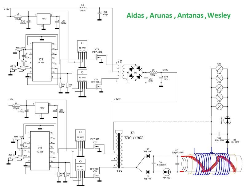
A circuit diagram has been found on a Russian website, freeenergylt.narod2.ru/Aidas. The diagram includes a pulse generator, which requires PCGU1000 equipment for the coils to function. There are discussions about the internal resonation design, involving a capacitor in parallel...
A thorough examination of the Kapanadze video reveals that the vertical coil is wound with copper tape, forming a capacitor that captures environmental particles with the assistance of high voltage. Experiments indicate that it charges easily with minimal power...
A Georgia Republic inventor, Tariel Kapanadze, claims to have invented a 5 kilowatt free energy generator. In a demonstration video, the device appears to produce copious amounts of energy from no visible source. More: The components apparently include a...

If the scope probes are not isolated, it is still possible to connect the grounding leads of the probes to point A while connecting the tips of the probes to points B and C. The resulting current traces will...
To estimate the input energy required for the pump circuit, the average voltage input (waveform D) is approximately 6V (12Vpp), while the average input current (waveform G) is around 1.5 - 2mA (8mApp). To sustain the loaded oscillations in...