
Key Illuminator Circuit

The circuit described functions as a momentary illuminator, designed to activate an LED for a duration of approximately 10 seconds upon pressing a switch (SI). The core components involved in this operation include a switch (SI), a capacitor (CI), and a transistor (Q1).
When the switch SI is pressed, it initiates the charging process of the capacitor CI. The capacitor accumulates charge and, once sufficiently charged, it maintains the base current of the transistor Q1. This action effectively turns the transistor on, allowing current to flow through the LED, thereby illuminating it.
The duration for which the LED remains lit is primarily determined by the capacitance value of CI and the resistance in the circuit that governs the discharge rate of the capacitor. The relationship between these components can be described by the time constant τ (tau), calculated using the formula τ = R × C, where R is the resistance and C is the capacitance. The LED will remain illuminated until the capacitor discharges to a level where it can no longer keep the transistor in the 'on' state.
In practical applications, this circuit can be adapted for various uses beyond simple illumination, such as in timers, alarms, or indicators where a brief period of light is needed. Adjustments to the capacitor and resistor values can tailor the timing to meet specific requirements, making this circuit versatile for different electronic projects. Used as a 10-second momentary illuminator, this circuit can be useful in other applications as well. Pressing SI charges CI, which holds Ql on and holds the LED lit for about 10 seconds.
Related Circuits
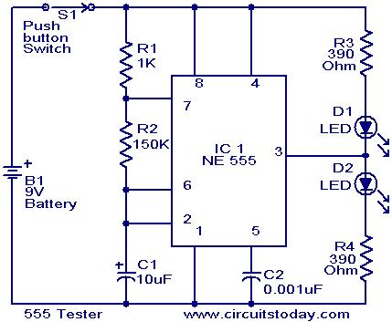
This schematic requires clarification. It is assumed that pin 2 is connected by a wire to pin 6, although this connection appears to be unclear. The circuit in question involves a schematic where pin 2 and pin 6 are interconnected....
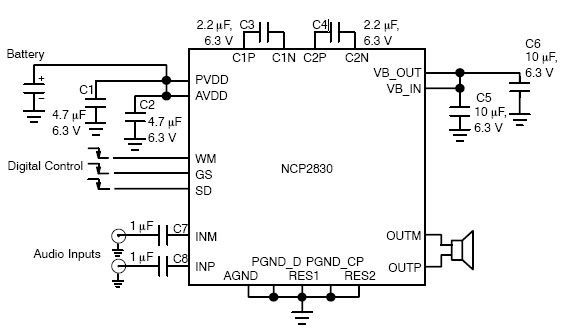
The NCP2830 audio power amplifier features high-quality audio performance with a total harmonic distortion plus noise (THD+N) of 0.04%. It offers low noise with a signal-to-noise ratio (SNR) of up to 100 dB and optimizes overall system efficiency, achieving...

The LTC3113 fixed frequency buck-boost DC-DC converter can be utilized to design various power supply circuits that operate with input voltages that are above, below, or equal to the output voltage. The topology integrated into the IC ensures low...
This circuit is permanently connected to a mains socket and is designed for trickle charging nickel-cadmium (Ni-Cd) batteries. In the event of a power outage, the lamp automatically turns on. An alarm sounder can be used in place of...
The latest addition to the collection of Infrared (IR) Repeater circuits, the Mark 5, is an enhanced version of the Mark 1 circuit and features an increased range. The Mark 5 Infrared Repeater circuit is designed to extend the range...
This DIY magnetic field sensor circuit is straightforward and capable of detecting both static magnetic fields and those that vary at audio frequencies. The unit is designed to be user-friendly and efficient. The magnetic field sensor circuit typically employs a...