
5 volts 3A Dc DC converter circuit design project using LTC3113 IC

The LTC3113 is a highly versatile DC-DC converter that operates efficiently across a wide range of input voltage conditions. Its ability to function as a buck-boost converter allows it to maintain a stable output voltage regardless of whether the input voltage is above, below, or equal to the desired output level. This feature is particularly beneficial in applications where the input voltage may fluctuate, such as battery-powered devices or renewable energy systems.
In terms of performance, the LTC3113 is designed to minimize noise, making it ideal for sensitive applications in radio frequency (RF) and precision measurement environments. The low noise operation is achieved through the use of a well-optimized control topology that minimizes switching noise and ripple.
The converter can deliver higher output currents in buck mode, which enhances its versatility in various applications. The integrated power MOSFETs feature a low RDS(ON) specification, which reduces conduction losses and improves overall efficiency. Additionally, the programmable switching frequency of up to 2 MHz allows designers to optimize the converter's performance based on the specific requirements of their application, including size constraints and electromagnetic interference (EMI) considerations.
Safety and reliability are paramount in the LTC3113 design. The integrated soft-start feature prevents inrush current during startup, while short-circuit protection and current limiting mechanisms safeguard the converter and connected loads from damage. Thermal overload protection further ensures that the device operates within safe temperature limits, enhancing its longevity and reliability.
The control mechanism of the LTC3113 is based on pulse width modulation (PWM), where the output duty cycle is regulated by the error amplifier's output (VC). This allows for precise control over the output voltage, ensuring that it remains stable under varying load conditions. The synchronous power switches, characterized by low gate charge, enable high-frequency operation while maintaining efficiency.
Overall, the LTC3113 is an advanced solution for designing compact, efficient, and reliable power supply circuits suitable for a wide range of applications, from consumer electronics to industrial systems. Its combination of features makes it a preferred choice for engineers seeking to implement robust power management solutions.Using the LTC3113 fixed frequency, buck-boost DC DC converter can be designed various power supplies circuits that operates from input voltages above, below or equal to the output voltage. The topology incorporated in the IC provides low noise operation, making it well suited for RF and precision measurement applications.
Higher output current is possible in step down (buck) mode. Integrated low RDS(ON) power MOSFETs and a programmable switching frequency up to 2MHz result in a compact solution footprint. Some features of the LTC3113 IC include <1 A shutdown current, integrated soft-start, short-circuit protection, current limit and thermal overload protection. The error amplifier output (VC) determines the output duty cycle of each switch. The low RDS(ON), low gate charge, synchronous power switches provide high frequency pulse width modulation control.
🔗 External reference
Related Circuits
An LED is usually a series resistor needed to ensure that the LED does not get too much power. The disadvantage of such resistance is that the current through the LED and thus the brightness changes as the voltage...
The AM transmitter circuit consists of an audio amplifier and an RF oscillator. The oscillator is constructed around transistor Q1 and its associated components. The tank circuit, which includes inductor L1 and variable capacitor VC1, is tunable from approximately...
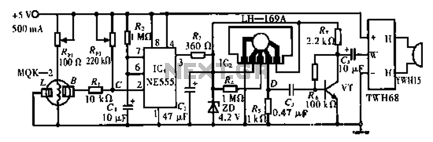
The circuit operates using the MQK-2 gas sensor, which detects the presence of combustible gases or smoke through surface adsorption. When gas is detected, the inter-electrode resistance (BL) decreases significantly. This change in resistance affects the voltage at node...

The robot requires a method for detecting obstacles (or other robots) without making physical contact. This capability allows the robot to determine whether to avoid or confront and investigate the obstacle based on its programming. This document outlines the...
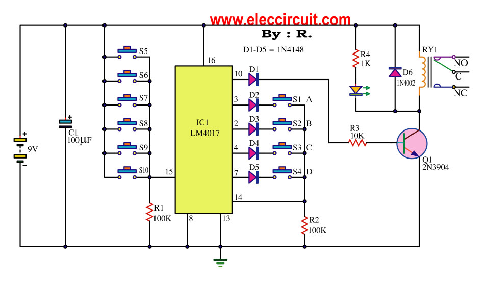
This key code switch circuit is an electronic circuit designed to replace conventional key switches, eliminating the need for physical key inserts. The key code switch circuit utilizes a microcontroller or a dedicated integrated circuit (IC) to interpret key codes entered...
This circuit utilizes inexpensive, commonly available components to generate a precise dial tone for telephone applications. The Intel 82C54 timer-counter (U1) produces square wave signals at frequencies of 350 Hz and 440 Hz, which are subsequently filtered by resistors...
Warning: include(partials/cookie-banner.php): Failed to open stream: Permission denied in /var/www/html/nextgr/view-circuit.php on line 713
Warning: include(): Failed opening 'partials/cookie-banner.php' for inclusion (include_path='.:/usr/share/php') in /var/www/html/nextgr/view-circuit.php on line 713