
Understanding Circuit Schematics
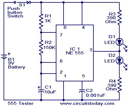
The circuit in question involves a schematic where pin 2 and pin 6 are interconnected. To fully understand the implications of this connection, it is essential to analyze the roles of these pins within the broader context of the circuit.
Pin 2 may serve as an input or control signal, while pin 6 could function as an output or feedback point, depending on the specific application of the circuit. The connection between these two pins suggests a potential interaction that may influence the circuit’s performance, such as signal conditioning or control logic.
In examining the schematic, it is crucial to identify the components associated with these pins. For instance, if pin 2 is connected to a resistor or capacitor, this could affect the timing characteristics or the impedance seen by the signal. Additionally, understanding the voltage levels and current flow between these pins can provide insights into the overall functionality of the circuit.
Further investigation into the surrounding components, such as transistors, operational amplifiers, or digital logic gates, will yield a more comprehensive understanding of how pin 2 and pin 6 interact. It is also advisable to refer to the datasheet or technical documentation for the specific components involved to clarify their operational parameters and constraints.
Ultimately, a thorough analysis of the schematic, including the identification of all relevant connections and components, will facilitate a clearer understanding of the circuit's behavior and the significance of the connection between pin 2 and pin 6.Here is a schematic that I need help understanding- On this circuit I`m assuming pin 2 is connected by a wire to pin 6 even though it doesn`t make.. 🔗 External reference
Related Circuits
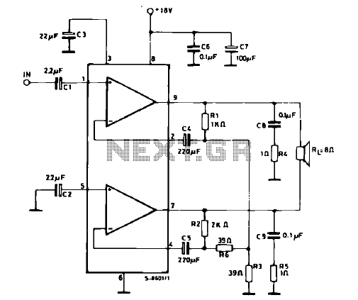
The schematic illustrates a 12 W Bridge Amplifier circuit diagram utilizing the TDA2007A, a class AB dual audio power amplifier. This amplifier is specifically designed for stereo applications in music centers, television receivers, and portable radios. As stated in...

This document illustrates the configuration of the high-precision, high-impedance OPA2111 amplifier. The total voltage circuit is designed for a magnification of Av = 10 (1 + 2R2 / R1), achieving a total gain of 1000 times. A gain stage...
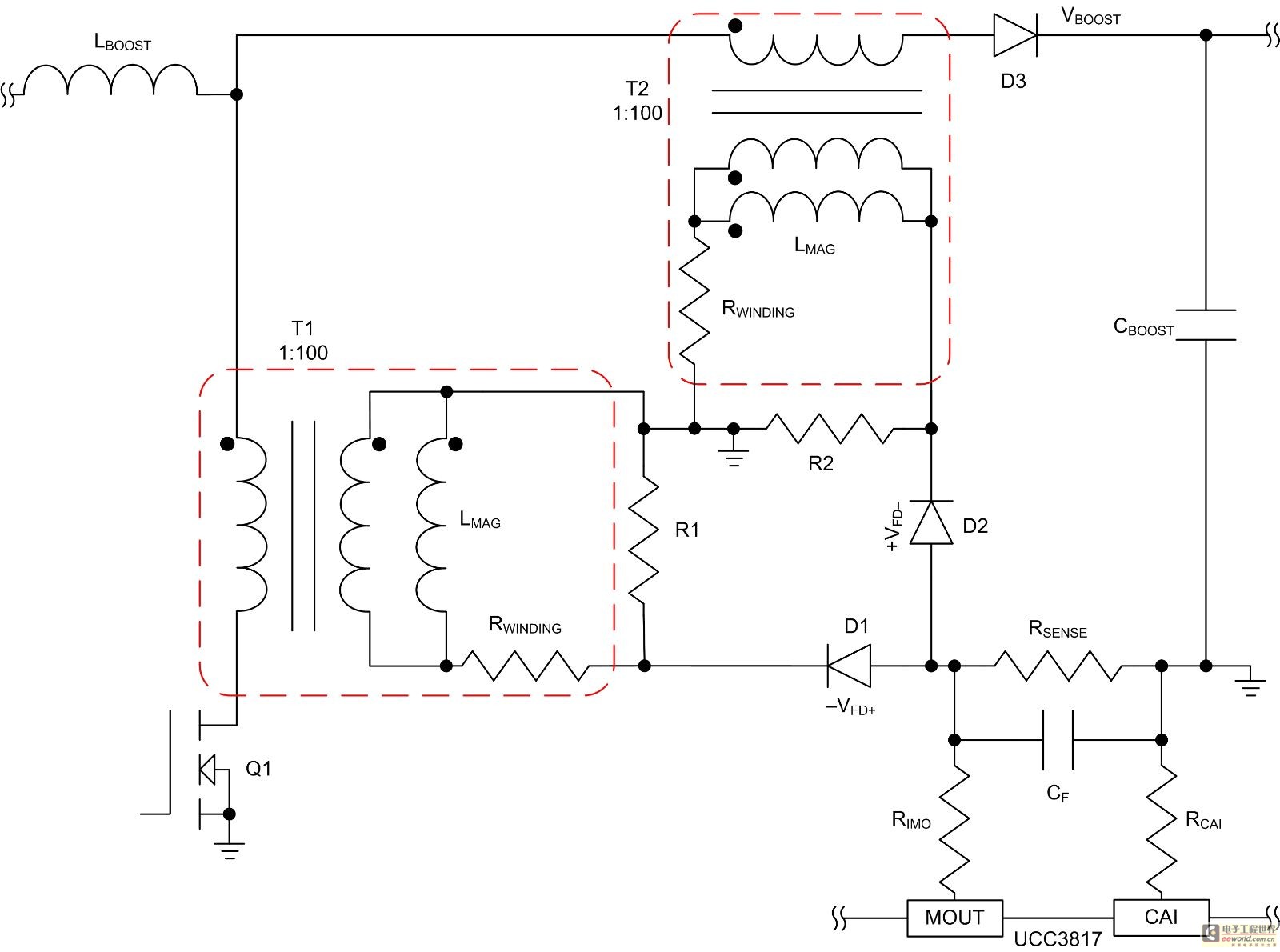
Mode control of the average current (CMC) is necessary to regulate the overall waveform of electric current during the rebuilding cycle. This text recommends selecting specific parameters related to the voltage transformer and outlines steps for designing a circuit...
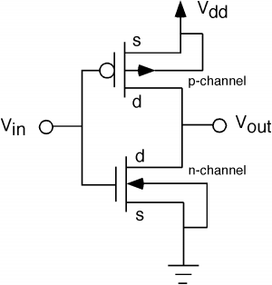
The fundamental issue presented is the perception that logic gates in a circuit seem to generate power from nothing, which contradicts the principles of physics. For instance, consider two NOT gates connected in series. It appears that the first...
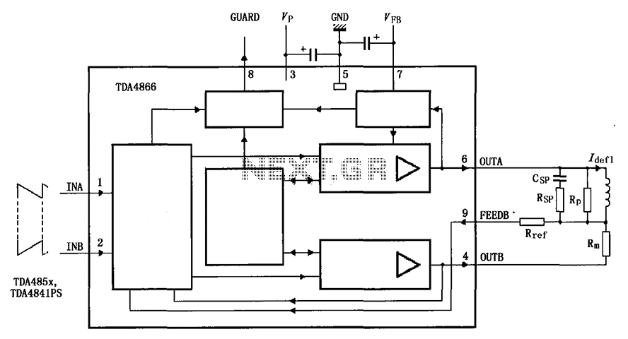
The TDA4866 is a 90-color power amplifier designed for vertical deflection systems, operating at a frequency range of 50 to 160 Hz. The CRMM circuit is implemented to ensure a high current drive input. The amplifier features a dual...
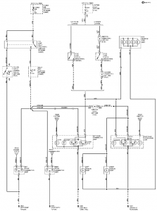
The connection and wiring between each part and component of the exterior lighting system of the vehicle includes elements such as the fusible link, junction block, tail light relay, cruise control, stop light switch, relay box, column switch, rear...
Warning: include(partials/cookie-banner.php): Failed to open stream: Permission denied in /var/www/html/nextgr/view-circuit.php on line 713
Warning: include(): Failed opening 'partials/cookie-banner.php' for inclusion (include_path='.:/usr/share/php') in /var/www/html/nextgr/view-circuit.php on line 713