
Keyless Entry Arduino
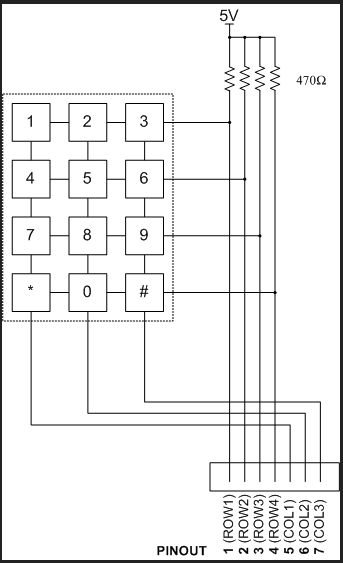
The described circuit involves a matrix keypad configuration, which is a common method for interfacing multiple keys with a limited number of input/output lines. In this case, the keypad utilizes a 3x4 matrix, consisting of 3 rows and 4 columns, enabling the detection of 12 keys using only 7 wires.
When a key is pressed, such as the number 8, it connects a specific row to a specific column. For example, pressing the number 8 connects ROW3 to COL2. The microcontroller continuously scans the rows and columns to identify which key is pressed by checking for a voltage change on the corresponding row and column lines.
To implement this, the microcontroller can be programmed to set each row to a low state sequentially while reading the column states. When the microcontroller sets ROW3 low, it will check COL2 for a low signal. If detected, it confirms that the key corresponding to that intersection (in this case, the number 8) has been pressed.
This efficient method reduces the number of required input lines, allowing for a compact design while still providing the functionality of a full keypad. The remaining wires are utilized for the other rows and columns, ensuring that the microcontroller can accurately detect all key presses within the matrix configuration.Example if you press number 8 it will effect the wire ROW3 and CLO2. By this the microcontrollercan determine what key was pressed with only 7 wires from the keypad. 🔗 External reference
Related Circuits
This project implements a network-connected water level sensor that measures the water level in the sump pit of a house. It is connected to the home network and reports the water level by broadcasting UDP packets, allowing any computer...
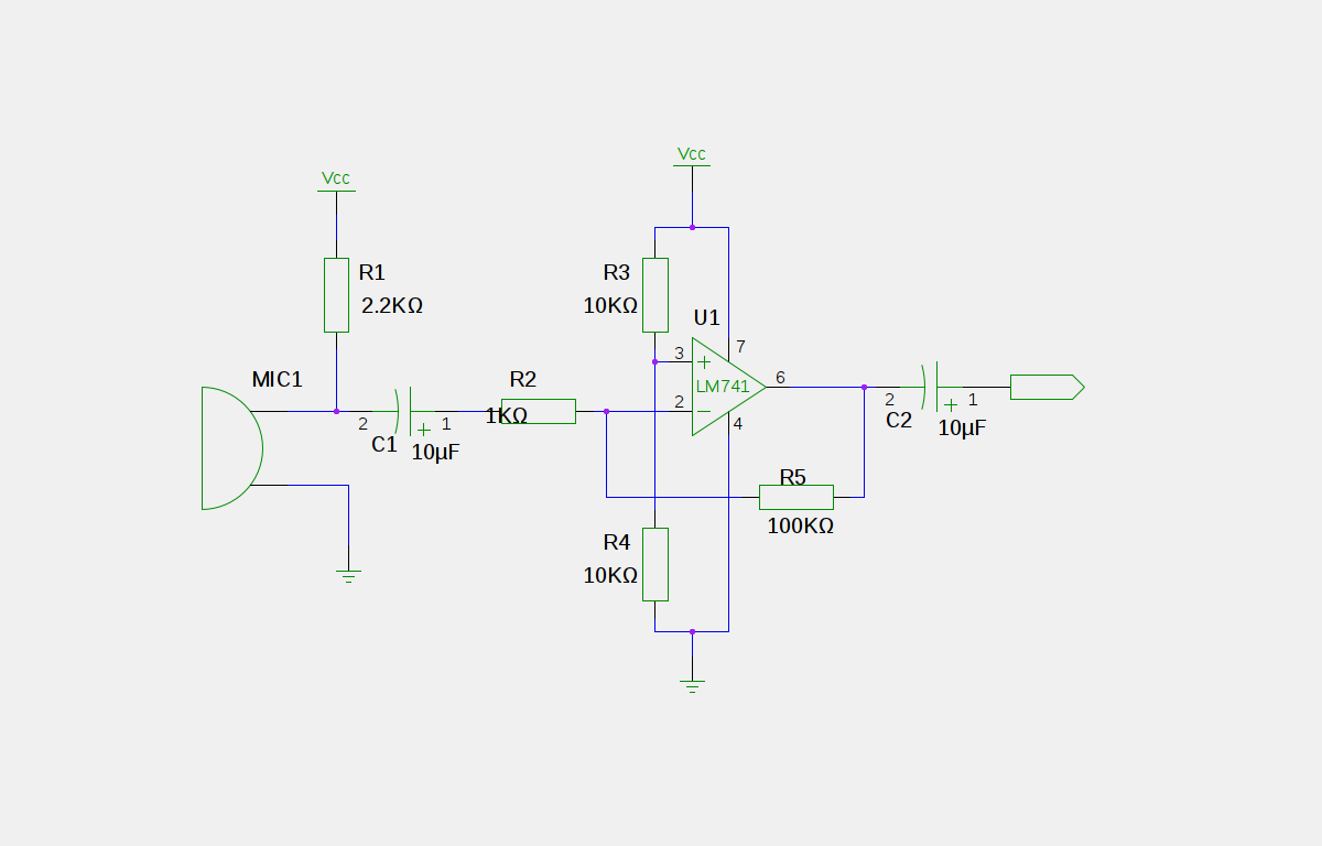
An electret microphone has been connected to an operational amplifier (op-amp), with the output directed to an Arduino microcontroller. The analog-to-digital converter (ADC) on the microcontroller converts a voltage range of 0 to 5 volts into a 10-bit number,...
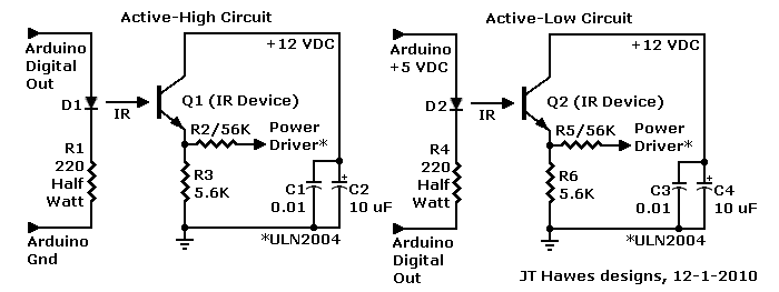
A Darlington transistor can enhance circuit performance, although it introduces slight complexity. The advantage of using a Darlington configuration lies in its capability to achieve low output impedance. The recommended component is the 2N6426 from Mouser, with alternatives such...
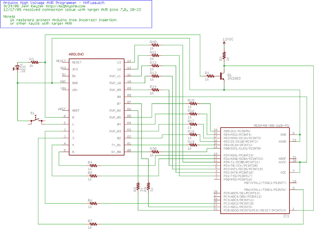
Fortunately, my trusty Arduino came to the rescue. I created an Arduino-based AVR programmer that uses the high voltage programming mode and can fix pesky fuses like RSTDISBL. The Arduino has just enough IO to implement the entire HV...

The core of the switch controller is an Arduino Nano microcontroller, which will serve as the interface between the dashboard switches, wireless steering wheel buttons, and the vehicle's lighting, indicators, windscreen wipers, and DigiDash2 GPS stopwatch. This setup facilitates...
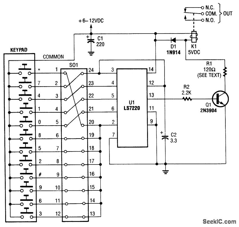
A keypad is used to input a four-digit access code, which can be programmed using jumpers on a 24-pin plug-in header and socket. The component U1 is an LST220, responsible for detecting the sequential four-digit data input. Upon entering...