
Water Level Sensor with Arduino Ethernet
The network-connected water level sensor project utilizes the MPX2010DP pressure sensor to accurately measure water levels in a sump pit. The sensor operates by measuring the pressure difference between two inputs, where one input is connected to the bottom of the pit via a hose, and the other is left open to the atmosphere. This configuration allows the sensor to provide a reliable measurement without being affected by variations in atmospheric pressure.
The MPX2010DP sensor outputs a voltage range of 0 to 25 mV, which is insufficient for direct analog readings by the Arduino. Therefore, an amplification circuit is implemented to boost this signal to a more usable level, typically around 5 V. The amplifier circuit is designed as an instrumentation amplifier, which enhances the output signal while maintaining accuracy. A trim potentiometer is included in the design to allow for fine-tuning of the amplification factor, ensuring that the sensor can provide both high readings when the water level is elevated and a good resolution for intermediate levels.
The Arduino microcontroller plays a central role in this project, as it reads the amplified sensor voltage from an analog input pin (A0) and transmits the data over the home network using UDP packets. This enables real-time monitoring of the water level from any computer connected to the network. The Arduino program is designed to be straightforward, facilitating easy data retrieval and processing.
To enhance usability, a command line interface is implemented, allowing for calibration adjustments without the need to modify and upload new sketches. The trigger levels for alerts can be set and stored in the EEPROM, ensuring that the settings persist even after power cycles.
Powering the system is achieved through a computer power supply, specifically utilizing the 5 V standby rail, which provides a stable and sufficient power source for the Arduino and sensors. This choice of power supply also offers flexibility for additional components in future expansions.
The project is housed in water-resistant electrical boxes to protect the sensitive components from environmental factors. The Arduino is placed in a separate enclosure with a transparent lid for easy monitoring of the circuitry. Future enhancements may include additional sensors for temperature monitoring and integration with mobile notification systems to alert users of significant changes in water levels. The current focus remains on successfully calibrating and installing the two sensors, followed by implementing a web server to display the results.This project implements a network connected water level sensor, measuring the level in the sump pit of my house. It`s connected to the home network and reports the water level by broadcasting UDP packets so that any computer can receive it and take action, such as sending out an alert or storing statistics.
Before we go any further, let me just po int out that the pressure sensor, MPX2010DP, used in this project exists in another version, MPX5010DP, that has an output voltage interval much better suited for this project. If only I had checked that I wouldn`t have needed to build any circuits or use any extra components at all.
The pressure sensor MPX2010DP measures the pressure difference between two inputs, from 0 to 10 kPa and outputs between 0 and 25 mV on it`s two output pins. (The MPX5010DP gives you between 0 and 4. 7 V output, ideal for direct connection to the analog inputs on Arduino. ) This means that we can use it to reliably measure the water level in a tank or pit, without being troubled by changes in air pressure The only thing we need to do is connect input 1 to a hose leading to the bottom of the pit and leave input 2 hanging in the air.
The MPX2010DP operates anywhere between 0 and 16 V and draws less than 10 mA, which means we can run it directly off the 5 V pin on the Arduino. (MPX5010DP operates between 4. 7 V and 5. 25 V with about the same current draw, so in that case it`s even more ideal) It`s also possible to run the amplifier circuit from the Arduino, if you decide to go down that road.
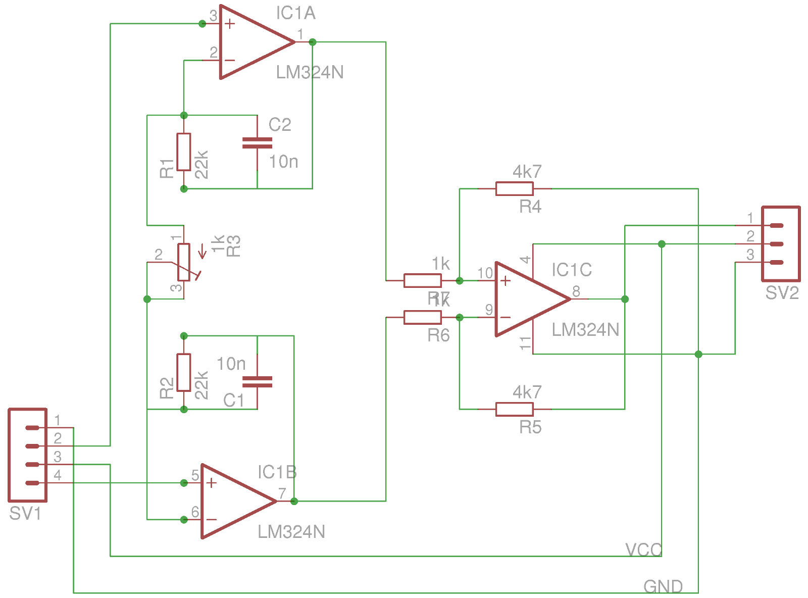
All this also means that you can run a long cable (I used shielded 4-wire telephone cable, but any 3-wire cable should be fine) from your Arduino to your sump pit or water tank. The amplifier circuit takes the input from the pressure sensor and amplifies the 25 mV maximum output to something more useful, like 5 V.
Initially I used the circuit from Practical Arduino, and it worked fine when supplied with 12 V. When powering it with only 5 V it wouldn`t give me enough gain, so I had to rework the resistor values. I also scrapped the fourth amplifier as it didn`t really do anything for me. In the end what I had was an instrumentation amplifier. There is one trim potentiometer. It can be used to adjust the amplification, i. e. the sensitivity of the sensor, so that you get a good high reading for when the water level is high, and a good resolution in between.
For the second sensor I have two sump pits I created a PCB. It`s the first PCB ever that I designed myself and the second ever that I made myself, so it`s not exactly perfect. Most notably I didn`t change the size of anything on the board so all lines and connectors are very small, making it a pain to drill and solder.
The program for the Arduino is pretty simple. I read the value from the analog input A0 and send it out as a broadcast UDP message. This allows me to receive the results on any computer in the house and do whatever I like with the results. So far I`m just monitoring the values. Of course I couldn`t leave it at that. For one thing, I need a way to calibrate the system and I don`t feel like modifying and uploading a new sketch for that, so I decided to create a serial port command line interface, allowing me to modify and read the trigger levels.
I also made sure that the values are stored to the EEPROM and read back from there whenever the program starts, so that I won`t have to redo it whenever I need to reset the Arduino. The Arduino and the sensors don`t draw a lot of current so any 5V (or higher) power source will do. I decided to a computer power supply from a disused Pico ITX case. I`m using the standby 5V rail to power the Arduino and sensors. This leaves me an assortment of 3. 3V, 5V and 12V rails that I can use for future projects. Computer power supplies are nice as you can run your Arduino from the 5V standby rail and power power it on and off through software.
(Pull one of the digital outputs high, connect the green wire to it and then pull the pin low to turn on the power supply. Pull the pin high again to turn it off. ) I used small and really cheap, although water resistant electrical connection boxes for the sensor and the electronics that live in the sump pit.
For the Arduino I got a slightly smaller box to hold it and the power supply. I opted for one with a transparent lid so that I can see the electronics. I also got a case with some extra height to leave room for future shield extensions. The first thing is to get yet another level sensor, for the second sump pit, wired up and to extend the sketch for that. Then there are all kinds of ideas for further sensors, maybe checking the temperature in and outside of the house and why not monitor the fridge and freezer I`m also thinking of connecting it to a mobile phone and enable the system to send me a text message whenever something unusual happens, such as the water rising above a specified level.
For now, however, I`ll be quite happy to get both sensors installed and calibrated and have my web server presenting the results. That should just be a few weeks off. 🔗 External reference
Related Circuits
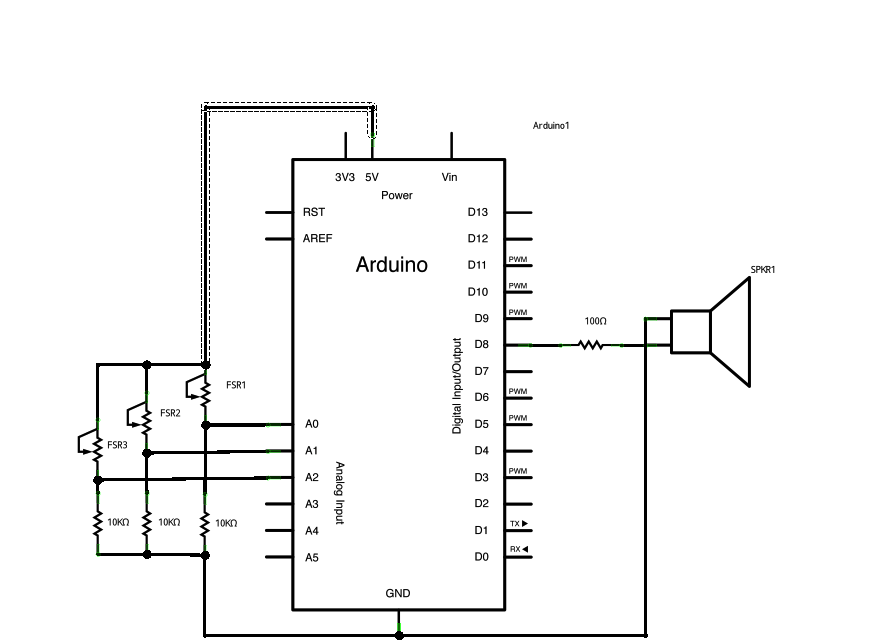
Power three force-sensitive resistors (FSRs) or any other analog sensor with 5V in parallel. Connect each sensor to analog pins 0-2, utilizing a 10K resistor as a reference to ground on each input line. The provided sketch reads three...
Interface the LCD with the 8051 microcontroller AT89S52. However, upon powering up the microcontroller, the LCD displays only black boxes. Multiple codes have been tried, but the output remains the same. The circuit has been simulated in Proteus, where...
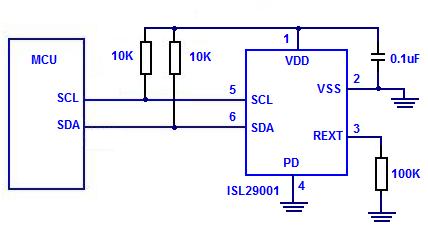
The Intersil ISL29001 is a digital light sensor designed to measure light intensity and easily interface with a microcontroller. The Intersil ISL29001 is a highly integrated digital light sensor that operates using a photodiode and an analog-to-digital converter (ADC) to...
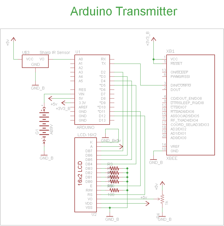
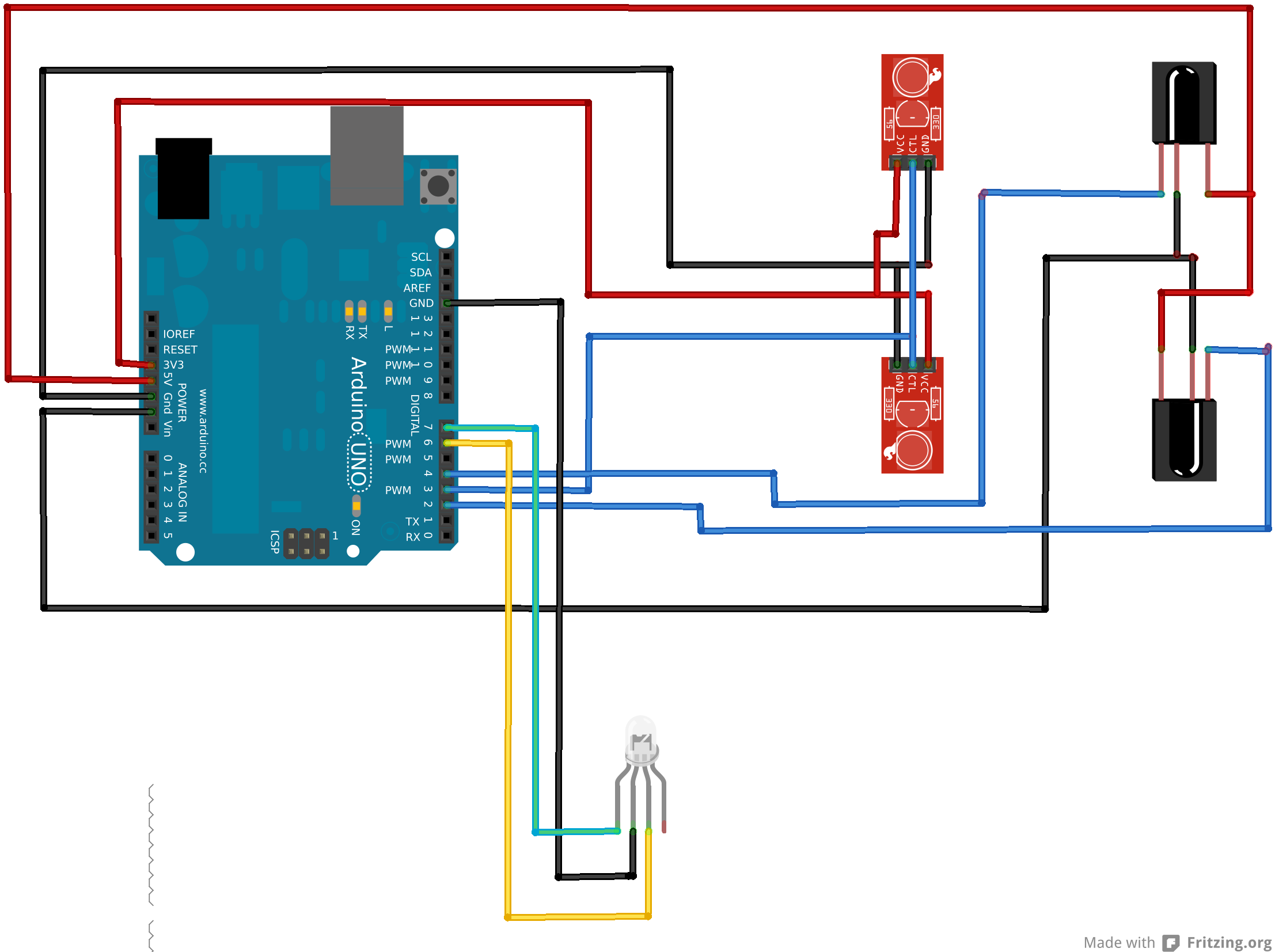
The schematic for the transmitter in this project consists of four main components: the Arduino UNO, the Sharp IR distance sensor, the XBee wireless modules, and a 16x2 LCD. The connections between these components are illustrated in the schematic....

In August 2007, an individual with a passion for photography acquired a Panasonic FZ30 digital camera and joined a forum on dpreview dedicated to Panasonic products. A fellow forum member, who was a programmer and electronics enthusiast, created a...
An Arduino Uno is connected to two infrared (IR) transmitters and their respective receivers. When one of the receivers detects a beam break, a strand of LEDs displays a pattern. While this setup functions correctly in principle, an issue...