
DIGITAL ENTRY LOCK
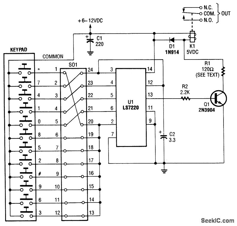
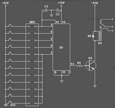
The circuit design features a keypad interface for user input, allowing for secure access control through a four-digit code. The keypad connects to a 24-pin header, where jumpers can be configured to set the desired access code. The LST220 (U1) serves as the core logic component, interpreting the signals from the keypad. It is designed to recognize a specific sequence of four digits, ensuring that only authorized users can gain access.
When the correct code is entered, a high signal is generated at pin 13 of U1. This signal is utilized to drive a transistor (Q1), which acts as a switch to control the current flow to the relay (K1). The relay is responsible for activating an external electric lock solenoid, thereby unlocking the door or access point.
The circuit should also include necessary debouncing mechanisms for the keypad to prevent false triggering due to mechanical noise when keys are pressed. Additional components such as resistors and capacitors may be used to stabilize the power supply to U1 and ensure reliable operation. Optional features could include LED indicators to provide visual feedback when the correct code is entered or audible alerts for incorrect entries.
Overall, this electronic schematic provides a straightforward and effective method for implementing a secure access control system using a keypad and relay mechanism.A keypad enters a four-digit access code, which is programmed via jumpers on a 24-pin plug-in header and socket. U1 is an LST220, which detects a four-digit sequential data input. When the correct data is entered into the keyboard, pin 13 of U1 goes high, which activates Q1 and K1.
K1 drives an external electric lock solenoid, etc. 🔗 External reference
Related Circuits
The Digital Combination Lock Circuit is a schematic for a simple electronic combination lock utilizing the LS7220 integrated circuit (IC). This password-protected digital lock can activate a relay to control any device by entering a preset combination of four...
The CT Scanner, short for computed tomography scanner, was invented in 1970, building on prior advancements in dedicated minicomputers. A high DC voltage is applied to the capacitors as X-rays enter the system. The chamber ionizes the xenon gas,...
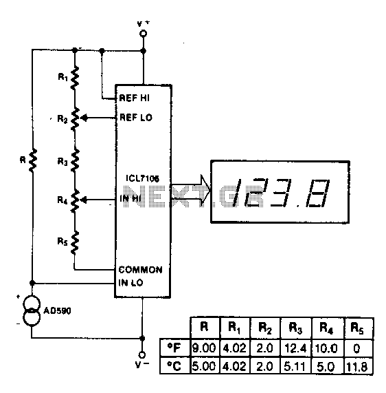
The maximum reading on the Celsius range is 199.9 °C, which is limited by the short-term maximum allowable sensor temperature. The maximum reading on the Fahrenheit range is 199 °F (93 °C), constrained by the number of display digits....
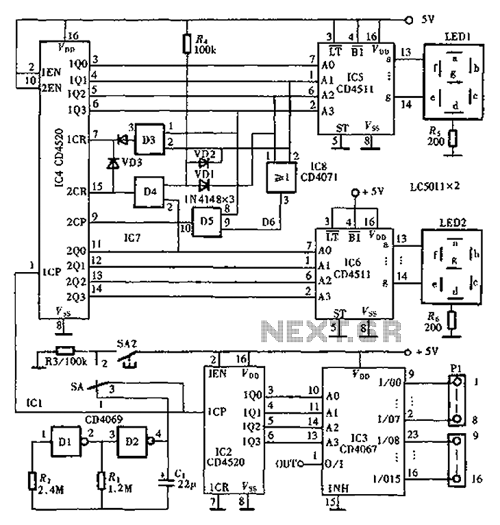
An automatic inspection circuit designed for the simultaneous detection and control of multiple production equipment. This inspection circuit can perform sixteen regular inspections of production equipment. It consists of a pulse generator, multiple inspection circuits, and an automatic inspection...
INTRODUCTION Digital to analog converters are one of the most commonly employed circuits in many applications involving digital video, signal processing, and testing. Digital to analog converters (DACs) serve a critical role in modern electronic systems by converting digital signals,...
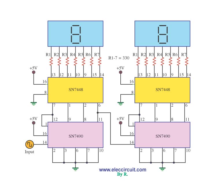
A decade counter circuit is an electronic circuit designed to perform a sequence of numerical calculations, allowing for either forward or backward counting. Forward counting refers to the circuit counting from smaller to larger numbers, while backward counting is...