
2x16 LCD and 4x4 keypad example
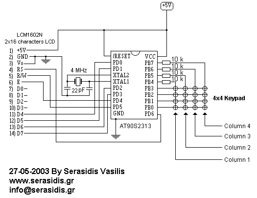
The circuit utilizes the AT90S2313 microcontroller, which is a member of the AVR family and is well-suited for embedded applications due to its low power consumption and versatility. The 2x16 LCD display provides a clear interface for outputting the pressed key values, while the 4x4 keypad allows for user input. The 4 MHz crystal oscillator ensures stable clock signals necessary for the microcontroller's operation.
To interface the LCD in 4-bit mode, the data lines are connected to pins PB4 to PB7 of the AVR, allowing for efficient communication with the display while conserving I/O resources. The keypad is connected in a matrix configuration, which enables the microcontroller to scan multiple keys using fewer pins. The 10 kΩ resistors serve as pull-up resistors, ensuring that the input pins are in a known state when not actively driven low by the keypad.
The scanning algorithm implemented in the source code sequentially enables each column of the keypad, reading the state of the keys. This method allows the microcontroller to detect which key is pressed by checking the status of the corresponding input pins. When a key press is detected, the microcontroller sends the appropriate value to the LCD, providing immediate feedback to the user.
This circuit serves as an excellent platform for learning about microcontroller interfacing, LCD operation, and keypad scanning techniques. It can be further expanded by adding additional features such as debounce logic for the keypad or implementing more complex user interactions through the LCD display.A very simple circuit forexperiments with AT90S2313, 2x16 LCD display and 4x4 keypad. The clock is based on 4 MHz crystal, but you can use any other crystalbetween 1-4 MHz. The keys with the name "A", "B". "F" are typed to the LCD with numbers 10-16. Because the AVR has only 15 I/O pins we work the LCD display with 4-bit data bus. The 4 resistors (10 k) are protecting the AVR from anyshortcut onthe columns of the keypad when AVR is scanning the keys by changing the pinstatus from input to output. I wrotethe source code ina simple form, that it means I haven`t made any economy to the flash memory, for understanding the way howthis circuit works.
The AVR configure the PortB as PB0-PB3 inputs and PB4-PB7 outputs. Onthe beginning, the AVR puts the pin PB4 at logic `0` to enable the column 1 (the first 4 keys) and reads the status of the keys. If we have pressed any of the 4 first keys then the AVR sends the number of the key to the LCD display.
If we have not pressed any of 4 first keys, the AVR puts the PB4 at logic `1` and PB5 at logic `0` to enable the secondcolumn. Reading the statusof the keys and display the result to LCD, etc, until the 16th key is been read. After that, the circuit starts again to read from the 1st key (1st column). 🔗 External reference
Related Circuits
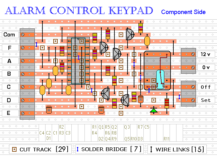
This keypad is designed for use with a modular burglar alarm system but can also be applied in various other applications. Pressing a single key will activate the relay, while entering a four-digit code of your choice will deactivate...
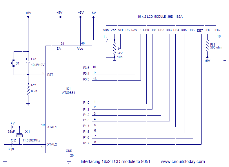
Interfacing a 16x2 alphanumeric LCD module with the AT89S51 microcontroller. The circuit diagram, theory, and program are included. JHD162 LCD module pinout and commands are provided. The integration of a 16x2 alphanumeric LCD module with the AT89S51 microcontroller involves several...
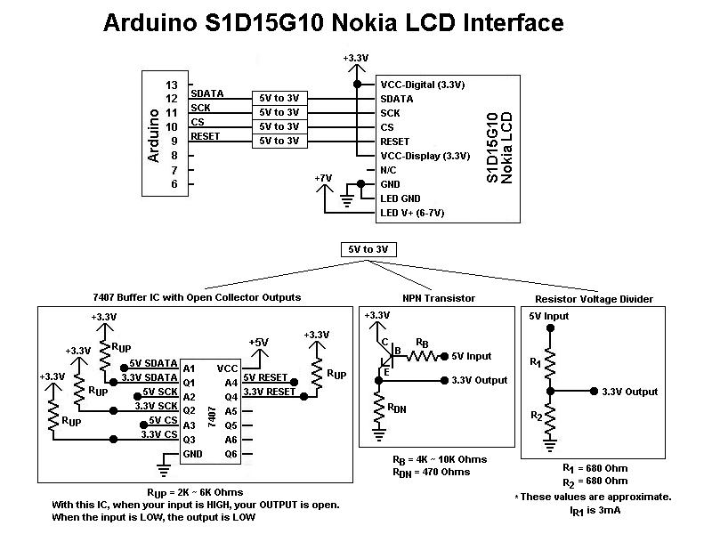
This is the first color graphic LCD display encountered. Initial assumptions were made regarding the connections, specifically that the Chip Select (CS) and RESET pins could be tied high for simplicity, based on previous experience with TTL logic. However,...
Here's PLL FM transmitter circuit from china. This circuit uses the familiar 2SC1971 for final power amplifier stage. The PLL controller of the FM transmitter use SAA1057 and PIC16F628 (download HEX file). More: If want to change the active...

If you are developing applications for the PIC MCU and miss debugging tools or don't have enough I/O pins for a parallel LCD interface in your design, this serial interface can help print debug messages and/or reduce the pin...
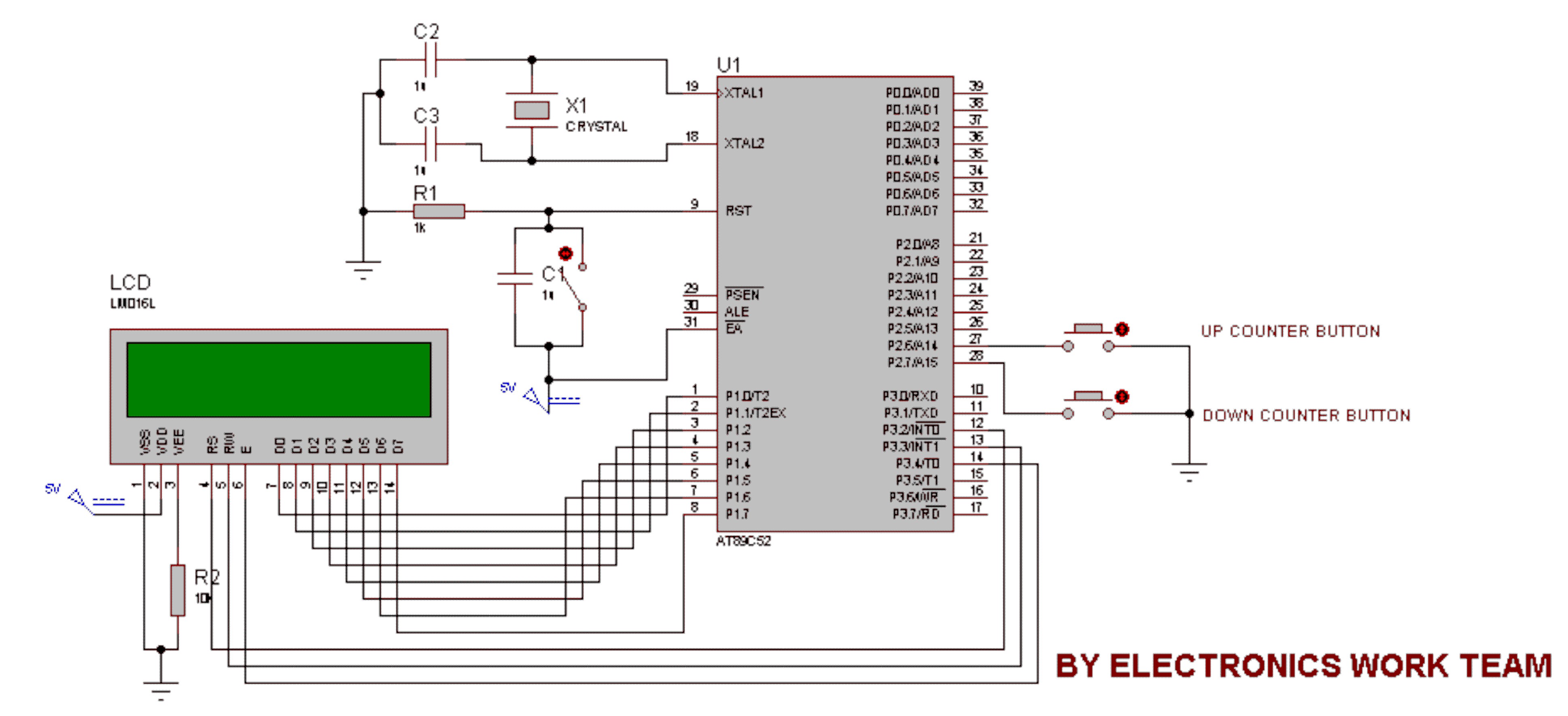
This circuit utilizes a 16x2 LCD to display a count value using an 8051 microcontroller. The maximum count value is set to 99. The circuit consists of the 8051 microcontroller, a 16x2 LCD, and two switches designated for incrementing...
Warning: include(partials/cookie-banner.php): Failed to open stream: Permission denied in /var/www/html/nextgr/view-circuit.php on line 713
Warning: include(): Failed opening 'partials/cookie-banner.php' for inclusion (include_path='.:/usr/share/php') in /var/www/html/nextgr/view-circuit.php on line 713