
L200 DC Motor Speed Control

The L200 is a versatile integrated circuit designed for various applications, including speed control in permanent magnet motors. The circuit typically consists of the L200 chip, which regulates voltage and current to provide efficient motor control.
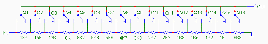
In this schematic, R1 and R2 are critical components that set the reference voltage and current limits, allowing for precise control over motor speed. The values of these resistors can be calculated based on the desired speed and motor characteristics. A potentiometer can also be employed in place of R2 for adjustable speed settings.
Additional components may include capacitors for filtering and stability, as well as diodes for back EMF protection from the motor. The L200 also requires appropriate power supply connections, typically a DC voltage source, to operate effectively.
The output of the L200 is connected to the motor, where it modulates the voltage supplied to the motor windings. By adjusting the resistance values, the user can finely tune the motor's speed to meet specific application requirements, ensuring optimal performance and efficiency.
Overall, the L200 provides a robust solution for speed control in permanent magnet motors, offering flexibility and precision in various electronic applications.This diagram tells us about how to use L200 device for the speed control of permanent magnet motors. By means of R1 and R2, we can obtain the desired speed,.. 🔗 External reference
Related Circuits
The traditional potentiometer is implemented with an electrical contact that slides over a resistive layer. An example of a well-known audio-grade potmeter is the Alps Blue. A high-end (good and costly) alternative is the rotary switch. This device consists...
The Atmel Flash devices are ideal for developing, since they can be reprogrammed easy and fast. If you need more code space for your application, particularly for developing 89Cxx projects with C language. Atmel offers a broad range of...
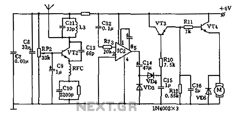
The homemade wireless remote control circuit diagram illustrates a motor remote control transmitter circuit. The circuit utilizes a 555 timer along with resistors R1, R2, RP1, diodes VD1, VD2, and capacitor C1 to create a variable duty cycle astable...
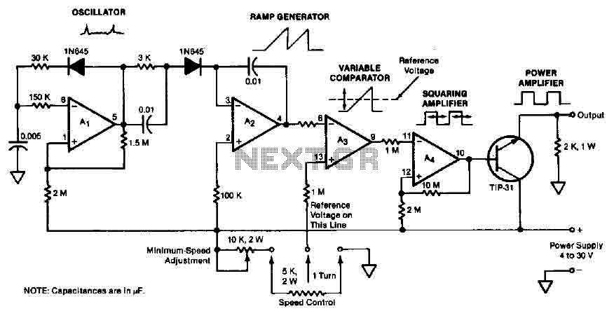
The quad operational amplifier circuit provides a pulse width modulation control ranging from 0 to 100 percent. The controller utilizes an LM3900 and operates with a single supply voltage between 4 to 30 V. A 1 kHz oscillator amplifier,...
H-Bridge circuit utilizing transistors for the bidirectional control of a DC motor. Integrated circuits (ICs) containing H-Bridges are employed to simplify the drive circuit. The L293D is a dual H-Bridge motor driver, allowing for the control of two DC...
This circuit is an ETHERNET controller I use the PIC18F452 and the mikroC C Compiler. I use also the JAVA SCRIPT information you can get from www.w3school.com I Control 8 outputs throw the WEB and transfer time information also....