
Input pulse width controller circuit
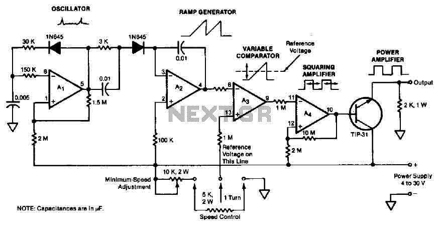
The described quad operational amplifier circuit serves as an efficient pulse width modulation controller, leveraging the LM3900 operational amplifier to achieve precise control of motor speed or other applications requiring variable power delivery. The single supply voltage range of 4 to 30 V allows for versatile integration across various electronic systems. The core of the circuit is the 1 kHz oscillator amplifier, which serves to generate a stable frequency for the pulse width modulation.
The Az ramp generator plays a crucial role in producing a linear voltage ramp, which is essential for generating the desired pulse width. By applying this ramp signal to the inverting input of comparator A3, the circuit can effectively compare the ramp voltage with the control voltage. The comparator's output produces a pulse train whose width is modulated in accordance with the control voltage. This feature enables the circuit to adapt to different operational requirements, such as varying motor speeds based on external conditions or user input.
The adjustable potentiometer or external feedback source can be integrated into the circuit to provide dynamic control over the pulse width. This adaptability allows for real-time adjustments, making the circuit suitable for applications such as motor speed control in automotive systems or other machinery where speed regulation is critical.
The amplifier stage A4, with its gain of 10, functions as a pulse squaring circuit, ensuring that the output pulse train is sharp and well-defined, which is vital for driving the subsequent TIP-31 transistor. This medium-power transistor acts as a power amplifier, capable of handling significant current loads while providing efficient power delivery to the motor or other connected loads. The overall design of the circuit emphasizes reliability and performance, making it a valuable component in various electronic control systems.The quad operational amplifier circuit yields full 0 to 100 percent pulse width control. The controller uses an LM3900 requires only a single supply voltage of 4-30 V. The pulse repetition frequency is set by a 1 kHz oscillator amplifier that integrates AI. The oscillator feeds the Az ramp generator, which generates a linear ramp voltage for each pulse oscillator. The ramp signal feeds the inverting input of comparator A3, the control voltage feeds speed non-inverting input.
Thus, the output of the comparator is a 1 kHz pulse train, pulse width that changes linearly with control voltage. The control voltage may be provided by a _ adjustable potentiometer or an external source of feedback as an engine speed detection circuit. Depending on the setting of control voltage, the pulse duration can be set at a value between zero (zero average dc voltage applied to the motor) to full repetition period of pulses (voltage applied to the motor equal to voltage DC power supply).
An amplifier stage (A4) with a gain of 10 acts as a pulse squaring circuit. TIP-31 medium-power transistor is driven by the A4 and serves as a distinct stage of power amplifier. 🔗 External reference
Related Circuits

The circuit's current exceeds the load carried by the rated current meter, prompting the user to immediately cut off the power supply to address the overload. Pressing the reset button restores power, making the system simple, convenient, and practical....
The figure illustrates a bilateral band modem circuit utilizing the NE561B component. The input modulating signal operates at a loading frequency of f0 = 1 MHz. When the AM modulation signal is applied to the input terminal of the...

Dual power for each load refers to the operation of two power supplies working simultaneously to handle the electrical load. In the event of a power outage, a contact switch automatically closes all load circuits that are not powered...
The circuit performs two functions: signal level attenuation and inverse RIAA filtering. Signal attenuation is required to convert a 500 mV signal to a 2.5 mV signal. Inverse-RIAA filtering is necessary to achieve a flat frequency response, similar to...
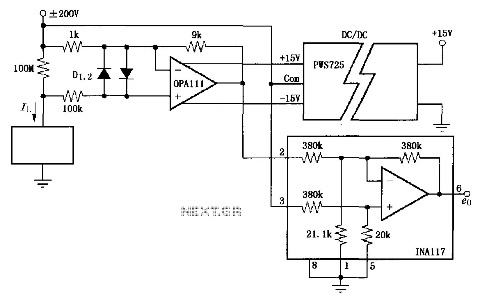
The circuit illustrated in FIG OPA111 is designed for measuring input buffer leakage current. The transistors D1 and D2, which are 2N3904 types, short the base and collector contacts while leaving the emitter open. When a power supply of...
If the reader arrived here via Google, they may have encountered other circuits for high-power LED driving that include many components such as inductors, operational amplifiers, various regulator ICs, transistor feedback networks, and microcontrollers. While those circuits tend to...
Warning: include(partials/cookie-banner.php): Failed to open stream: Permission denied in /var/www/html/nextgr/view-circuit.php on line 713
Warning: include(): Failed opening 'partials/cookie-banner.php' for inclusion (include_path='.:/usr/share/php') in /var/www/html/nextgr/view-circuit.php on line 713