
l297 stepper motor controller circuits
The L29 Stepper Motor Controller IC is designed to simplify the control of stepper motors in various applications, particularly where precise motor control is required. It supports both bipolar and unipolar motor configurations, making it versatile for different types of stepper motors. The ability to operate in multiple drive modes—half-step, full-step, and wave drive—enables smoother operation and finer control over motor positioning.
The internal PWM chopper circuits optimize the current flowing through the motor windings, enhancing efficiency and reducing heat generation. This feature is particularly beneficial in applications where power consumption and thermal management are critical. The requirement for only a clock, direction, and step input signals allows for straightforward integration with microcontrollers, minimizing the complexity of the control logic and reducing the processing load on the host microcontroller.
The L29 IC is packaged in both DIP20 and SO20 formats, which facilitates easy integration into existing designs. The choice between these packages allows designers to select the most suitable option based on space and thermal considerations. When paired with high-current drivers like the L293E or L298N, the L29 can handle larger motors and more demanding applications. Additionally, the option to use discrete transistors and Darlingtons provides further flexibility in circuit design, accommodating various power requirements and configurations.
In summary, the L29 Stepper Motor Controller IC is a robust solution for controlling stepper motors in microcomputer-controlled systems, combining ease of use, efficiency, and versatility for a wide range of applications.Four appearance drive signals for two appearance bipolar and four appearance unipolar footfall motors in microcomputer-controlled appliance is calmly implemented application L29 Stepper Motor Controller IC. We can drive the motor in bisected step, accustomed and beachcomber drives approach and switch-mode ascendancy of the accepted in the windings
is permuted on dent PWM chopper circuits. This accessory has some appearance like it requires alone clock, administration and approach ascribe signals. Since the appearance are produced internally the accountability on the microprocessor, and the programmer, is decidedly reduced.
This accessory is army in DIP20 and SO20 packages. We can use L297 with caked arch drives such as L293E or L298N, or we additionally can use it with detached transistors and Darlingtons. 🔗 External reference
Related Circuits
The PWM pulse width modulation controller board enables 9S12/HCS12 microcontrollers or PIC microcontrollers to output 8 channels, each capable of delivering 5 DC amps, while incorporating current sensing for the PWM waveform. This PWM driver circuit is suitable for...
An average ability amplifier characterized by acceptable overall quality, while being simple in construction. It is frequently used in live loudspeakers. The design incorporates high-quality FET transistors, specifically HEXFET technology, which are voltage-controlled rather than conventional bipolar transistors. The...
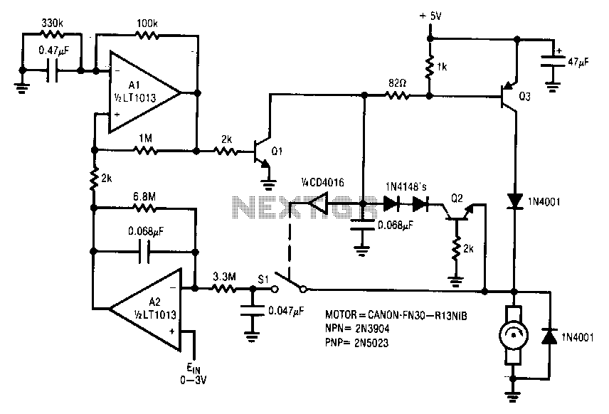
This circuit is particularly applicable to digitally controlled systems in robotic and X-Y positioning applications. By operating from a 5-V logic supply, it eliminates the need for additional motor drive supplies. The tachless feedback mechanism saves both space and...
This circuit automatically activates and deactivates a motorcycle's headlight, functioning independently of both the light and ignition switches, as long as the battery is fully charged. The initial stage employs a 220-ohm resistor and ZD1 to keep transistor Q1...
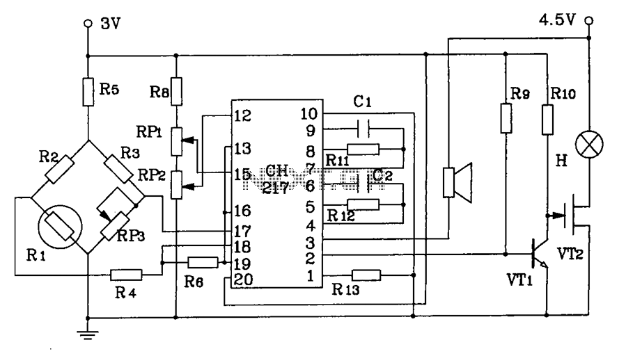
CH217 is a monolithic gas detection alarm integrated circuit. The gas detection alarm circuit diagram includes R1 as the gas sensing probe, where the resistance increases as the gas concentration decreases linearly. RP3 is used to adjust the output...
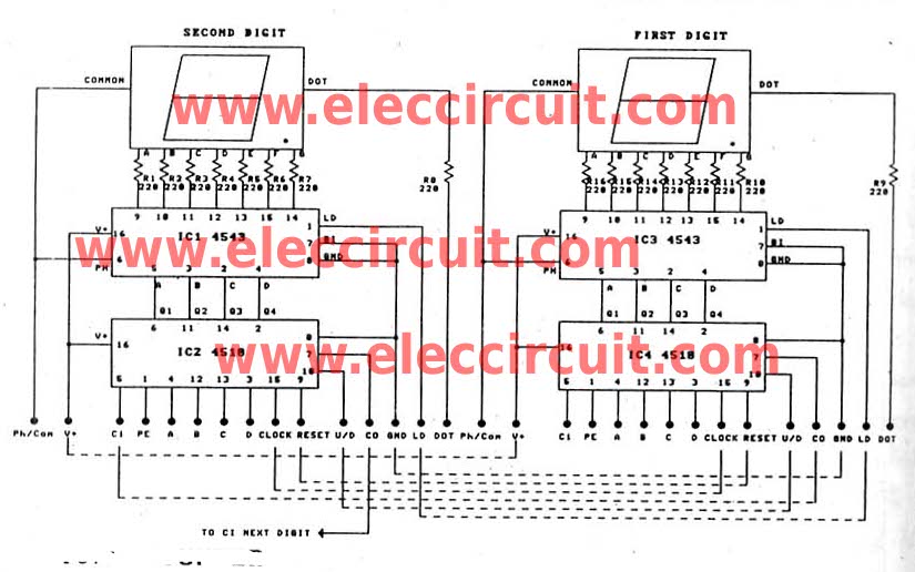
This is a versatile digital counter circuit that is cost-effective due to the basic components available in many electronic shops. The digital counter circuit is designed to count pulses and display the count on a digital readout, typically using a...