
CH217 monolithic gas gas gas detection alarm integrated circuits the circuit diagram of gas detection alarm
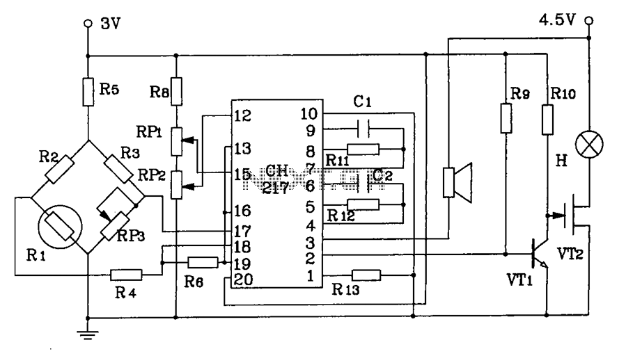
The CH217 integrated circuit is designed for gas detection applications, providing a reliable and efficient solution for monitoring gas levels in various environments. The primary component, R1, functions as the gas sensing probe. This probe exhibits a unique characteristic where its resistance changes inversely with the concentration of the target gas; as gas concentration decreases, the resistance of R1 increases linearly. This behavior is critical for accurate gas detection and monitoring.
The circuit employs RP3, a potentiometer, to fine-tune the output level of the amplifier, ensuring that the signal can be adjusted to meet specific application requirements. This feature allows for flexibility in the circuit's operation, accommodating different gas types and concentrations.
Additionally, resistors R6 and R7 are incorporated into the circuit to extract two distinct danger forecast reference signal voltages. These reference voltages are essential for determining the threshold levels at which the gas detection alarm will activate. By monitoring these voltage levels, the circuit can effectively signal when gas concentrations reach potentially hazardous levels, ensuring timely alerts and safety measures.
Overall, the CH217 gas detection alarm circuit is a sophisticated and adaptable solution for gas monitoring, leveraging the properties of its components to provide accurate readings and reliable warnings in gas detection scenarios. CH217 monolithic gas, gas gas detection alarm integrated circuits, and gas detection alarm circuit diagram R1 is the gas sensing probe, the resistance increases just gas concen tration decreases linearly, RP3 used to adjust the output level of the amplifier, R6, R7 extract and two kinds of danger forecast reference signal voltage.
Related Circuits
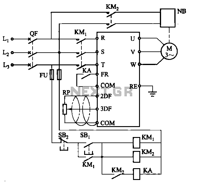
Electromagnetic brake motors consist of a motor and an electromagnetic brake, forming a standard assembly. The circuit diagram is provided. In this configuration, FR represents the forward run and stop command terminal, while the intermediate relay KA is employed...
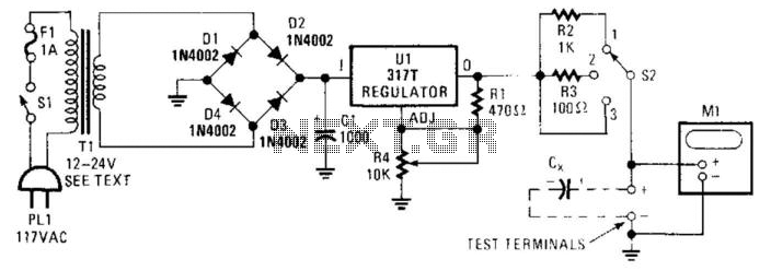
Sometimes electrolytic capacitors that are stored for a period may exhibit high leakage currents. Before utilizing these capacitors, it may be necessary to reform them. This power supply can be employed for the reforming process. Adjust resistor R4 according...
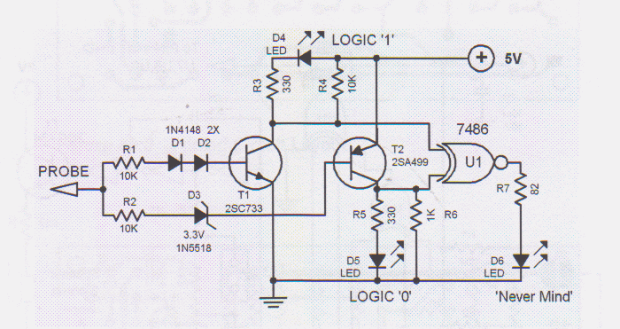
Logic testers are simple yet very useful devices for testing digital circuits. A logic probe can be designed in various ways. Logic testers, commonly referred to as logic probes, are essential tools in the field of digital electronics. These...
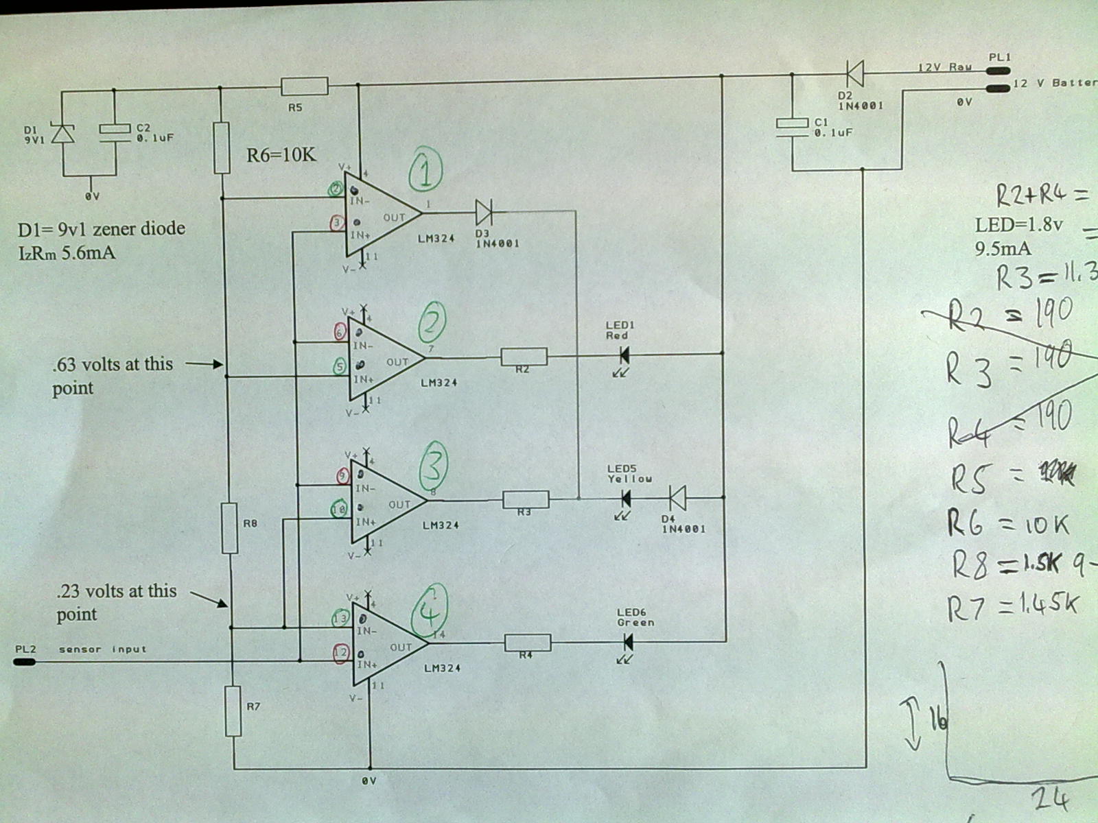
A 12V power supply is connected to the positive terminal, allowing current to flow through a protection diode and a capacitor that smooths the voltage. A zener resistor (R5) limits the current to the zener diode, which regulates the...
During nighttime, when no light falls on LDR1, it offers a high resistance at the base junction of transistor T1. Consequently, the bias is significantly reduced, and T1 does not conduct. This effectively removes the common terminal of IC1...

The transmitter is constructed on a Printed Circuit Board (PCB). This board incorporates track inductors for L1, L2, and part of L3. The section surrounding Q1 functions as the oscillator section, with the oscillation frequency determined by L1, C4,...