
A versatile and cheap digital counter circuits by CD4510 & CD4543

The digital counter circuit is designed to count pulses and display the count on a digital readout, typically using a seven-segment display. The circuit can be implemented using a variety of basic components, including logic gates, flip-flops, and resistors, making it accessible for hobbyists and beginners in electronics.
At its core, the counter utilizes a series of flip-flops configured in a binary counting arrangement. Each flip-flop represents a single bit, and the total number of flip-flops determines the maximum count of the circuit. For example, a circuit with four flip-flops can count from 0 to 15 in binary.
The counting process is initiated by applying a clock signal to the flip-flops. Each rising edge of the clock signal triggers the flip-flops to change state, effectively incrementing the count. The output from the flip-flops can be connected to a decoder circuit that translates the binary output into a format suitable for driving the seven-segment display.
To enhance the functionality of the counter, additional features such as reset and enable inputs can be incorporated. The reset input allows the user to set the counter back to zero, while the enable input can be used to pause counting, providing greater control over the counting process.
Power supply considerations are also important in the design of the circuit. Typically, a 5V DC power supply is sufficient to operate the logic components reliably. Proper decoupling capacitors should be placed close to the power pins of the integrated circuits to minimize noise and ensure stable operation.
In summary, this digital counter circuit is an excellent project for those looking to explore digital electronics. Its simple design, reliance on basic components, and versatility make it an ideal choice for educational purposes and practical applications.This is versatile digital counter circuit, that as a cheap due to basic components you can buy in many electronic shop. My friend said the some circuits that.. 🔗 External reference
Related Circuits
The circuit employs two Light Dependent Resistors (LDRs) arranged in series with a separation of approximately half a meter. This configuration allows each LDR to detect the presence of a person entering or exiting the room. The processed outputs...
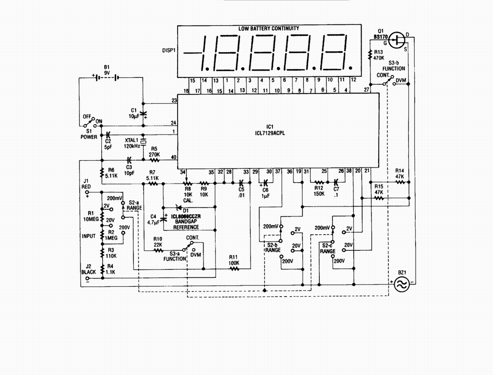
Single-chip digital voltmeter. This 4 1/2-digit DVM circuit is built around a Maxim ICL7129ACPL A/D converter and LCD driver. An ICL8069 CCZR 1.2-V band-gap reference diode is used for accuracy. The described circuit is a single-chip digital voltmeter (DVM) utilizing...

This design circuit is a tone control circuit that utilizes the popular Baxandall configuration, a straightforward circuit layout that allows for continuous boost and cut control. The circuit is inexpensive to construct and is frequently implemented in commercial products....

Some good inverter circuits I found oscillate at approximately 50 to 60 Hz. They are likely capable of handling up to two amps; any more than that will cause them to automatically shut off. If there are questions, please...
This small transistor tester employs a simple visual indication system to perform a quick go/no-go check on both NPN and PNP transistors. When testing a functioning NPN transistor, the green LED (D1) will flash, while the red LED will...
Low distortion bass and treble control for an amplifier. Circuit diagram. Electronics project. The low distortion bass and treble control circuit is designed to enhance the audio quality of an amplifier by allowing precise adjustments to the low and high-frequency...
Warning: include(partials/cookie-banner.php): Failed to open stream: Permission denied in /var/www/html/nextgr/view-circuit.php on line 713
Warning: include(): Failed opening 'partials/cookie-banner.php' for inclusion (include_path='.:/usr/share/php') in /var/www/html/nextgr/view-circuit.php on line 713