
L4970A Easy 5V 10A Switching Regulator circuit
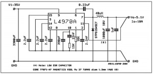
The described power supply circuit operates at a nominal output of 5V with a maximum current rating of 10A, making it suitable for various applications that require significant power. The core of the circuit is the L4970A, a high-efficiency switching regulator that allows for compact design and effective thermal management.
The L4970A is designed to operate with a wide input voltage range, typically from 8V to 40V, which provides flexibility in sourcing the input power. It employs pulse-width modulation (PWM) to regulate the output voltage, ensuring stable performance under varying load conditions. The switching frequency can be adjusted based on the application requirements, allowing for optimization of efficiency and component size.
For the circuit to function correctly, it is crucial to ensure that the input supply can continuously provide the required 10A current. This may involve using a suitably rated transformer or power adapter, along with appropriate fuses and protection circuitry to prevent overcurrent conditions.
The layout of the circuit should be designed to minimize parasitic inductance and resistance, which can impact performance, especially at higher currents. It is advisable to use thicker traces or PCB tracks for the power paths and to place decoupling capacitors close to the IC to stabilize the input voltage.
Additional components that may be included in the design are input and output capacitors to filter voltage spikes and ensure smooth operation. Inductors are also crucial in the design, as they store energy during the switching cycles and help maintain output voltage stability.
Overall, this power supply circuit is a practical solution for those requiring a reliable 5V source at 10A, with the L4970A providing a robust and efficient means of regulation. Interested builders are encouraged to gather the necessary components and begin assembly, focusing on good practices in soldering and layout to achieve optimal performance.Friends that seek 5V 10A power supply circuit small-sized and build easy. I begs for to advise this circuit. It is 10A switching regulator by use IC L4970A. Then build easy as an example integrated readymade circuit. Important point be power supply input must have 10A current sizes then can give power get enough. The detail is other of the circuit almost must not fine to decorate anything. If friends take an interest try seek buy the integrated circuit and other equipment. come to try build immediately yes. Disclaimer All files are found using legitimate search engine techniques. This site does not and will not condone hacking into sites to create the links it list. We will and do assume that all links found on the search engines we use are obtained in a legal manner and the webmasters are aware of the links listed on the search engines. If you find a URL that belongs to you, and you did not realize that it was "open to the public", please use the report button to notify the blogmaster of your request to remove it or it will remove within 24 hours.
This is not an invitation for webblog haters to spam with requests to remove content they feel that is objectionable and or unacceptable. Proof of URL ownership is required. NOTICE: This Blog Has Already Been Reviewed And Accepted By Blogger. com 🔗 External reference
Related Circuits
The DC values of op-amp offsets cannot always be assumed to remain constant when delivering AC outputs. No device is perfectly symmetrical in terms of maximum positive slew rate compared to maximum negative slew rate. As a result, there...
This circuit employs an HgCdTe demodulation device that can be cooled to 77K using liquid nitrogen. It utilizes a constant current bias for the demodulation device, which is connected to the input port. The voltage amplification factor is 200,...
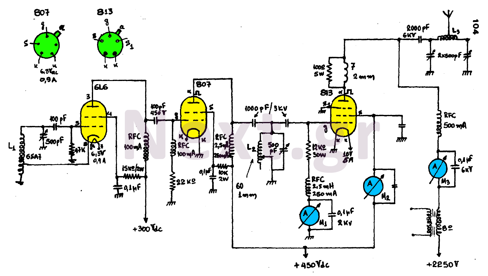
The circuit consists of three main stages and provides the antenna with a power output of 300 watts, contingent upon proper tuning. The first stage is an oscillator featuring an oscillating coil L1, which is commercially available as a...
A simple electronic key code lock circuit that requires few external components can be constructed using this schematic diagram. This electronic key code lock circuit is based on a common 555 timer circuit and other standard components. This low-cost...
The circuit utilizes the positive half-cycle of an alternating current (AC) to charge a battery. It offers a rapid charging speed and has the potential to extend battery life. This charger is commonly used with standard motorcycles, demonstrating excellent...
This circuit design was used to switch on device via a LED photocell arrangement (optocoupler) using components R1, C1, D1 and Q1. It produces a delay on powering up to ensure correct sequencing of certain equipment. A very simple...
Warning: include(partials/cookie-banner.php): Failed to open stream: Permission denied in /var/www/html/nextgr/view-circuit.php on line 713
Warning: include(): Failed opening 'partials/cookie-banner.php' for inclusion (include_path='.:/usr/share/php') in /var/www/html/nextgr/view-circuit.php on line 713