
Lamp Flasher

The described circuit functions as a flasher for continuous light lamps, transforming them into flashing lights. It is particularly effective for automotive applications and panel indicators, capable of driving loads up to 10 watts. The circuit operates within a voltage range of 3 to 24 volts DC, making it versatile for various applications involving existing on-circuit lamps.
To implement this circuit, the existing negative supply connection to the lamps must be interrupted. The circuit is then inserted between the lamp's connection and the negative supply. It is critical to maintain the correct polarity during installation to ensure proper operation and prevent damage to the components.
The circuit utilizes a capacitor, denoted as C1, which plays a pivotal role in determining the flashing frequency of the lamps. The capacitance value of C1 can be adjusted between 100 µF and 1000 µF or even higher, allowing for customization of the flashing rate. A larger capacitance will result in a slower flashing rate, while a smaller capacitance will yield a faster flashing effect. This adjustability provides flexibility in design, accommodating different visual requirements for the application.
In addition to standard incandescent lamps, the circuit is also compatible with LED lamps, expanding its usability in modern lighting applications. When using LEDs, consideration must be given to their forward voltage and current ratings to ensure that the circuit operates within safe limits.
Overall, this flasher circuit is a practical solution for converting static lighting into dynamic signaling, enhancing visibility and alertness in various environments. Proper installation and component selection are essential for optimal performance and reliability.This circuit was designed to provide that continuous light lamps already wired into a circuit, become flashing. Simply insert the circuit between existing lamp and negative supply. Especially suited for car or panel pilot lights, this device can drive lamps up to 10W. Ideal to operate 3 to 24V DC existing on-circuit lamps. LED operation is also possible. * Break lamp(s) to negative supply connection(s), then insert the circuit between existing lamp(s) connection(s) and negative supply (respecting polarities!). * C1 value can be varied from 100 to 1000µF or higher, in order to change flashing frequ 🔗 External reference
Related Circuits
This high power led mood light is based on PIC16F628 and the ability of this mcu to produce PWM pulses. Varying pulse width we can produce millions of color combinations using only the three basic colors. So only one...

This circuit is essentially an 8W inverter circuit designed to drive an 8W fluorescent lamp from a 12V power supply. It utilizes an inexpensive inverter based on a ZTX652 transistor. The inverter will operate efficiently to convert the DC...
This is a simple LED flasher using two 2N3904 transistors. Classic astable multivibrator using 2 transistors. Transistor is not critical. Try these: 2N4401, 2N2222, NTE123A, NTE123AP, NTE159, TUP/TUN and those in your junk box, you may find that most...
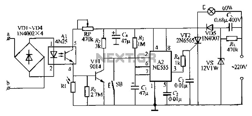
The lamp base circuit integrates an NE555 timer and optocouplers to automatically activate the light when a phone call is received at night. The lamp will self-extinguish after a delay. Additionally, a switch allows manual control of the lamp....
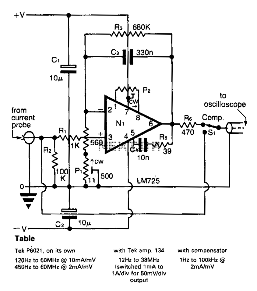
A clip-on current probe, like the Tektronix P6021, is a valuable tool for displaying current waveforms on an oscilloscope. However, it has limitations in low-frequency response. Specifically, the P6021 is sensitive to a range of 2mA/mV, and frequencies below...
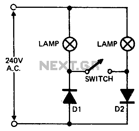
When setting up photographic floodlamps, it is sometimes desirable to operate the lamps at lower power levels until actually ready to take the photograph. The circuit allows the lamps to operate on half-cycle power when the switch is open...