
lan tester circuit
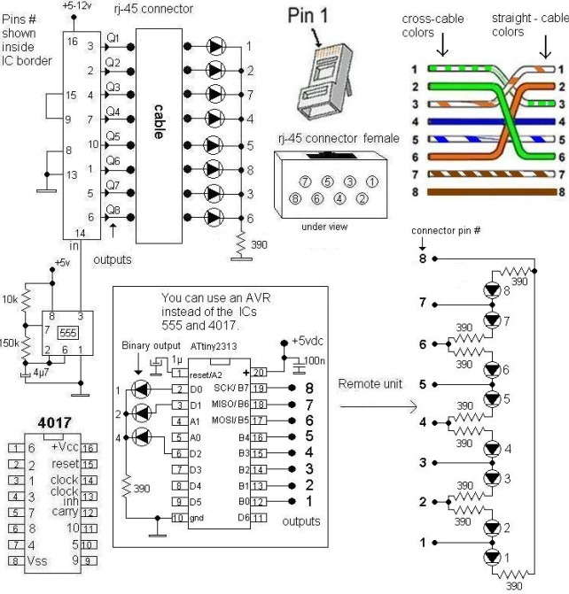
This LAN tester circuit, as designed by Vassilis Stergiopoulos, is versatile and can be implemented in two distinct configurations. The first configuration leverages the timer IC555 in conjunction with the decade counter 4017, facilitating a straightforward approach for testing LAN connections. The IC555 timer operates in astable mode to generate pulse signals, while the 4017 decade counter sequentially counts these pulses, providing a visual indication of the connection status through LEDs or other output devices.
The second configuration employs the ATtiny2313 microcontroller, offering a more advanced and programmable solution. This design allows for enhanced functionality, such as customizable testing protocols and the ability to interface with other digital components. The microcontroller can be programmed to display results on an LCD or transmit data to a computer for further analysis.
The DC battery tester circuit designed by Matthew B. serves a practical purpose in measuring voltages across a range from 1.5V to 9V. Utilizing a straightforward resistor network, the circuit can accurately assess battery health and provide a visual representation of the voltage level through the panel meter. The inclusion of specific resistor values ensures that the circuit operates within safe parameters, preventing damage to the meter or the circuit itself.
The remote control tester circuit is particularly useful for troubleshooting infrared remote controls. By incorporating the TSOP1738 infrared receiver module, this circuit detects signals emitted by the remote and provides immediate feedback through an audible tone. This feature simplifies the process of identifying operational issues with remote controls.
The low resistance connection tester utilizes a 741 operational amplifier configured in differential mode. This setup is effective for testing various connections, such as cables and solder joints, by measuring small resistance values. The circuit's design allows for quick identification of faulty connections, which is crucial in maintaining the integrity of electrical systems.
Lastly, the flame, gas, and smoke detector circuit plays a vital role in safety and security systems. By integrating with alarm systems, this circuit can trigger a relay to activate an alarm in the event of a hazardous condition. The schematic and component list provided facilitate easy assembly and implementation of this essential safety device. Security systems utilizing closed loop wiring can benefit from these designs, although considerations for potential tampering must be addressed to ensure system reliability.This LAN tester circuit originally designed by Vassilis Stergiopoulos. This LAN tester circuit optionally has two designs. The first design is built based 2 main ICs that are timer IC555 and decade counter 4017. The second design is based microcontroller chip ATtiny2313 (the other kind of microcontroller should be work). The first design circuit ( 555. Here the circuit diagram of DC battery tester designed by Matthew B. This circuit can be used to measure DC battery from 1. 5V up to 9V. Component Parts List: R1 = 18K Ohm R2 = 240 Ohm R3 = 8. 2K Ohm R4 = 3K Ohm R5 = 10 Ohm M1 = Panel Meter (Anyone will. Here is the remote control tester circuit. This circuit is really a simple and easy tester for verifying the basic operations of an infrared remote control unit. It is low-cost and very easy to construct. The tester is designed around infrared receiver module TSOP1738. Operation of the remote control is identified by a tone from. Here the low resistance connection tester which can be used as cable or wire tester, soldered joints and other types of connection with resistance value between 0.
25 and 4 ohm. Notes This simple circuit uses a 741 op-amp in differential mode as a continuity tester. The voltage difference between the non-inverting and inverting inputs is. Flame, gas and smoke detector for fire alarm. You can combine this circuit with alarm circuit. The output will be the relay which switch on and switch off the alarm. Schematic diagram: The list of components needed: Download include the explanation of the circuit: Download link A Many security systems use a closed loop of wires and switches arranged so that whenever a door or window is opened, the loop will be broken and the alarm will sound. An obvious problem is that someone can tamper with the system, short out the loop, and later on, come back and burglarize the.
🔗 External reference
Related Circuits
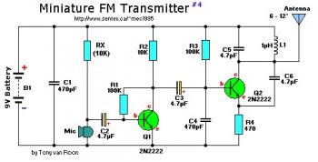
This small FM band transmitter utilizes only two 2N2222 transistors and is capable of transmitting signals up to 1 kilometer away, provided there are no obstacles between the two antennas. The circuit features a microphone preamplifier stage with the...

This schematic diagram illustrates a single-chip Theremin circuit. A Theremin is an electronic musical instrument that detects hand movements to control tones and frequency. The circuit employs two separate Colpitts LC oscillators to generate a beat frequency. The frequencies...
A highly beneficial project involving a crystal tester circuit, also known as an xtal tester circuit, constructed with only a few components. The circuit forms an oscillator that will only oscillate if the crystal under test is functioning properly....
Charging a mobile phone or cellphone battery presents a significant challenge while traveling, as a power supply source is often not readily available. If the cellphone remains switched on continuously, its battery can deplete within five to six hours,...
Mobile phone chargers available in the market are quite expensive. The circuit presented here serves as a low-cost alternative to charge mobile telephones or battery packs with a rating of 7.2 volts. The proposed circuit design utilizes a straightforward approach to...
This circuit utilizes an LM339 quad voltage comparator to create a time delay and manage a high current output at low voltage levels. Approximately 5 amps of current can be achieved using two fresh alkaline D batteries. Three of...