
Single Chip Theremin Circuit
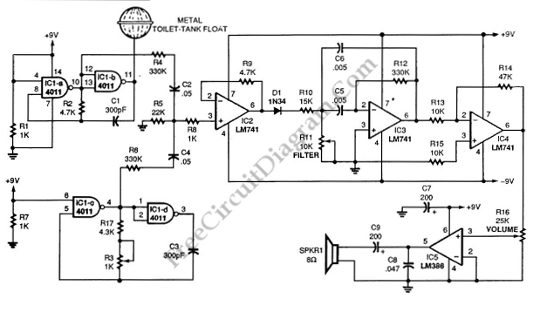
The Theremin circuit operates on the principle of heterodyning, where two frequencies are combined to produce a new frequency that is the difference between them. The two Colpitts oscillators, which are configured to operate at slightly different frequencies, generate signals that are mixed together. The resulting beat frequency is produced when the oscillators' outputs are combined. This beat frequency can vary based on the proximity of the user's hand to the metal probe, allowing the player to control pitch and tone through hand movements.
The 4011 quad gate is essential for generating the high-frequency oscillation, which is crucial for achieving the desired audible output range. The choice of 250 kHz allows for a broad spectrum of audible frequencies to be produced when the oscillators interact. The subsequent amplification stage, utilizing the LM741 operational amplifier, enhances the mixed signal's amplitude, ensuring that the rectification process can effectively isolate the audio signal from the high-frequency components.
The diode D1 serves as a rectifier, converting the mixed AC signal into a DC signal that represents the audio beat frequency. The adjustable bandpass filter, IC3, is critical for refining the audio output, allowing specific frequencies to be emphasized while attenuating others, thus tailoring the sound produced by the Theremin. Finally, the audio signal is further amplified by IC4 before reaching the power amplifier IC5, which drives the output to speakers or headphones, translating the electronic signals into audible sound.
The use of a metal toilet-tank float as a hand probe enhances sensitivity, allowing for more precise control of the Theremin's pitch and tone. This design choice underscores the importance of using appropriate materials in sensor applications to optimize performance. Overall, this schematic represents a sophisticated approach to electronic music synthesis, leveraging the principles of oscillation, mixing, and amplification to create an interactive musical experience.This schematic diagram show a single chip Theremin circuit. Theremin is an electronic music instrument which sense hand movement to control the tones/frequency. This Theremin circuit uses two separate Colpitts LC oscillators to produce a beat frequency. The frequencies of two Colpitts LC oscillators are mixed and then rectified. This rectificat ion demodulate the mixed signal to get the beat frequency which is in audible range. This beat frequency or difference is the real Theremin`s output. The oscillator is operated at high frequency (inaudible) to get wide audible frequency range of beat frequency when two oscillator output is mixed. This circuit uses a 4011 quad gate to construct the high frequency oscillator operating at 250kHz. Here is the schematic diagram of the circuit: The metal probe that is used to sense your hand produces only small frequency shift in term of percentage of original frequency, that`s why we need to derive the beat frequency to get wide audible frequency range as the result of high frequency shifting.
The IC2, an LM741 is used to amplify the mixed signal before rectification. The D1 will rectify the mixed signal to detect the audio (the beat frequency). This audio signal is then filtered by an adjustable bandpass filter IC3. The further audio amplification before power amplifier IC5 is done by IC4. The metal toilet-tank float is used for the hand probe since is has better sensitivity than a simple wire antenna, but any conductive material will work. [Circuit`s schematic diagram source: seekic. com] 🔗 External reference
Related Circuits
An electromagnetic vibration table or feeder is designed to move small objects along a specific track or cylindrical path through forced vibrations. This device can be custom-built to facilitate the movement of items along a rail tube. The vibration...
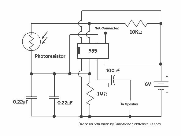
A light Theremin constructed using an oscilloscope panel, enhanced with a Joule Thief circuit. The design incorporates a 10 K variable resistor for pitch control and a 20 K variable resistor for volume control. The circuit is powered by...
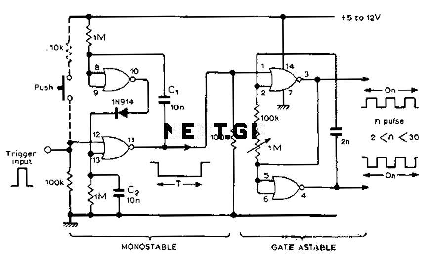
Each trigger input can produce a fixed number of pulses, with the range being from 2 to 30. The specific number is determined by the frequency-controlled settings of 1 megohm. A monostable gated unsteady power supply circuit can be...
The schematic for an infrared burglar alarm circuit is depicted in Figure 1. The infrared transmitter operates as a multivibrator with an oscillation frequency of 40 kHz, utilizing the NE555 integrated circuit (IC2), along with resistors R1 and R2...
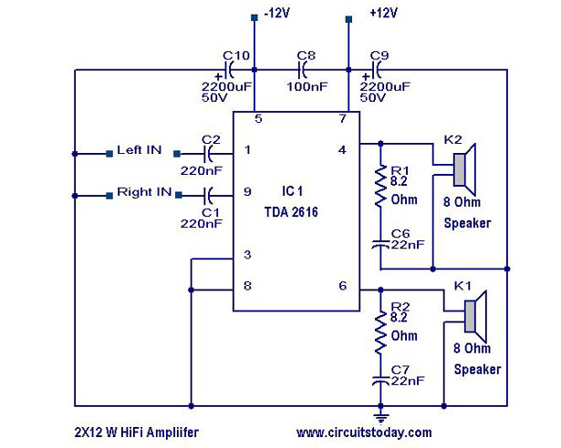
A simple Hi-Fi amplifier circuit diagram with a schematic for creating an audio amplifier design using the TDA 2616 IC. This is a stereo power amplifier suitable for radio, tape, and television applications, delivering 2 x 12 watts, totaling...
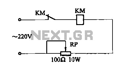
This circuit controls a load, specifically a DC brushless fan, based on a temperature comparison with a setpoint. The transducer utilized is a diode in the forward bias configuration. When forward biased, the forward voltage drop across the diode...