
lantern dimmer circuit

The lantern dimmer/flasher circuit is designed for versatility, allowing for both dimming of incandescent lamps and flashing of LED lights. The core components include resistors, capacitors, and transistors, which work together to create a stable and responsive circuit. The triac is crucial for controlling the power delivered to the load, enabling smooth dimming and flashing operations. The diac serves to trigger the triac at a specific voltage, ensuring that the circuit operates effectively within the desired parameters.
The touch dimmer feature enhances user experience, allowing for intuitive control of light intensity without mechanical switches. The use of a CMOS IC for touch applications indicates a modern approach to circuit design, providing reliability and compactness. The RFI noise suppression circuit is an important addition, ensuring that the operation of the dimmer does not interfere with other electronic devices.
The LED flasher aspect of the circuit is particularly useful during festive seasons, providing a reliable and adjustable lighting effect for decorative purposes. The ability to adjust the flashing frequency and duty cycle allows users to customize the visual output according to their preferences. The inclusion of a DC power supply input enhances the circuit's flexibility, enabling it to be powered from various sources.
Overall, this circuit design exemplifies a practical application of electronic components to achieve multifunctionality in lighting control, catering to both aesthetic and functional requirements.Here the circuit diagram of Lantern dimmer/flasher designed by Tony Van Roon: Electronic parts List: R1 = 100K R2 = 100K R3 = 100K R4 = 100K R5 = 3K9 R6 = 3K9 R7 = 470 R8 = 100 R9 = 220, 1/2 watt P1 = 5K C1, C3 = 10uF/16V C2 = 0. 01uF, ceramic T1. This simple 220V light dimmer circuit can be used to adjust the brightness of mains lights. It also ca n be used to adjust the speed of AC motors. It uses a triac, diac and has a radio-frequency interference (RFI) noise suppression circuit built into it as well. Schematic diagram: Component part: R1 = 10K R2. Here the 220V AC lamp touch dimmer circuit. By only touching this touch dimmer you are able to increase the light intensity of incandescent lamps in three stages.
The touch dimmer is designed all around 8-pin CMOS IC TT8486A/TT6061A especially produced for touch dimmer applications. In the beginning, when mains switch is "on", the lamp. This is a 220V LED flasher circuit which is intended as a reliable replacement to thermally-activated switches used for Christmas tree lamp-flashing.
This a cheap circuit and easy to build. Schematic diagram: Component Parts: R1_ 100K R2, R5_ 1K R3, R6_ 470R R4_ 12K C1_ 1000 µF 25V D1-D4_ 1N4007 D5_ SCR P0102D Q1_ BC327 Q2_ BC337 SK1_. This is the 200W lamp flasher circuit diagram. The frequency/speed of the lamp flashing can be adjust with the range of 1Hz to 5Hz. You can use the PR1 variable resistor (trimpot) to adjust the flashing speed. The duty cycle of lamp flashing can be adjusted using PR2 variable resistor. The DC input power supply. 🔗 External reference
Related Circuits
This compact amplifier is built around the TDA2003 integrated circuit, which can deliver 4W RMS at a 4-ohm load. The TDA2003 offers enhanced performance while maintaining the same pin configuration as the TDA2002. It retains the advantageous features of...
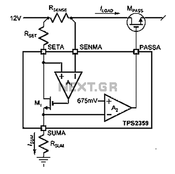
Amplifier A1 utilizes the voltage across the sense resistor sensors to monitor the load current ILOAD. The power management channel employs a similar circuit, with the distinction of integrating resistors RSENSE and RSET. Amplifier A1 is configured to measure the...

This is a simple power resumption alarm circuit that can be installed within the switch box. It emits beeping sounds when power is restored following a power outage. The power resumption alarm circuit serves as a practical solution for alerting...

This is an analog TV transmitter. Sound modulation is of the FM type with a 5.5 MHz carrier frequency, and video transmission follows the PAL standard. The frequency can be adjusted using capacitor C5, allowing tuning from 54 to...

A blocking material monitoring circuit is presented. When the optical path is obstructed by the material, the phototransistor VT1 turns off, which subsequently turns off transistors VT2, VT3, and VT4. This arrangement is coupled to a flip-flop configuration. When...
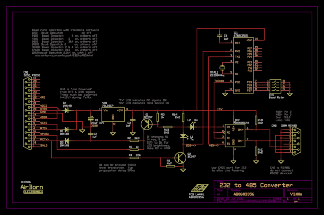
The new version of the RS485 interface addresses the issues associated with RTS control, which was a challenge in the previous design. However, implementing this solution requires a microprocessor, adding complexity to the design. This unit is currently being...