
Power Resumption Alarm circuit
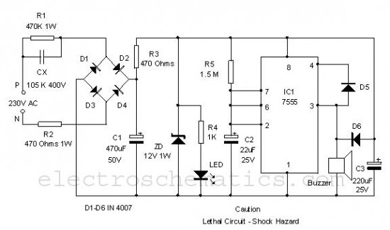
The power resumption alarm circuit serves as a practical solution for alerting users to the restoration of electrical supply after an interruption. The circuit typically comprises a few essential components: a power supply unit, a microcontroller or timer, a beeper or buzzer, and a relay.
Upon the restoration of power, the microcontroller or timer detects the voltage level and triggers the beeper to emit sound signals. The circuit can be designed to include a delay feature, ensuring that the alarm only activates after a specified period, which can prevent false alarms during transient voltage fluctuations that may occur immediately after power restoration.
The installation of the circuit within the switch box allows for a compact design, ensuring that it does not occupy additional space in the user's environment. The connections should be made with care to ensure that the circuit is safely integrated with the existing electrical system.
To enhance functionality, a visual indicator such as an LED can be added to provide a visual cue along with the audible alarm. Additionally, the circuit may include options for adjusting the volume of the beeping sound or even a reset button to silence the alarm after it has been triggered.
Overall, the power resumption alarm circuit is a straightforward yet effective device that enhances safety and awareness in environments prone to power outages.Here is a simple Power resumption alarm circuit that can be fixed inside the switch box itself. It gives beeps when the power resumes after a power failure. 🔗 External reference
Related Circuits
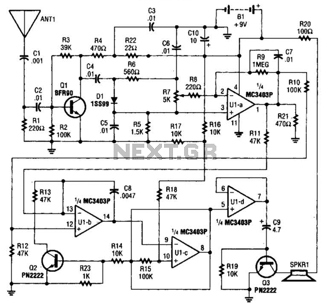
The circuit is constructed around a single integrated circuit (U1), specifically an MC3403P quad op-amp, three transistors (Q1-Q3), and several supporting components. It receives its input from the antenna (ANT1). The signal is processed through a high-pass filter composed...
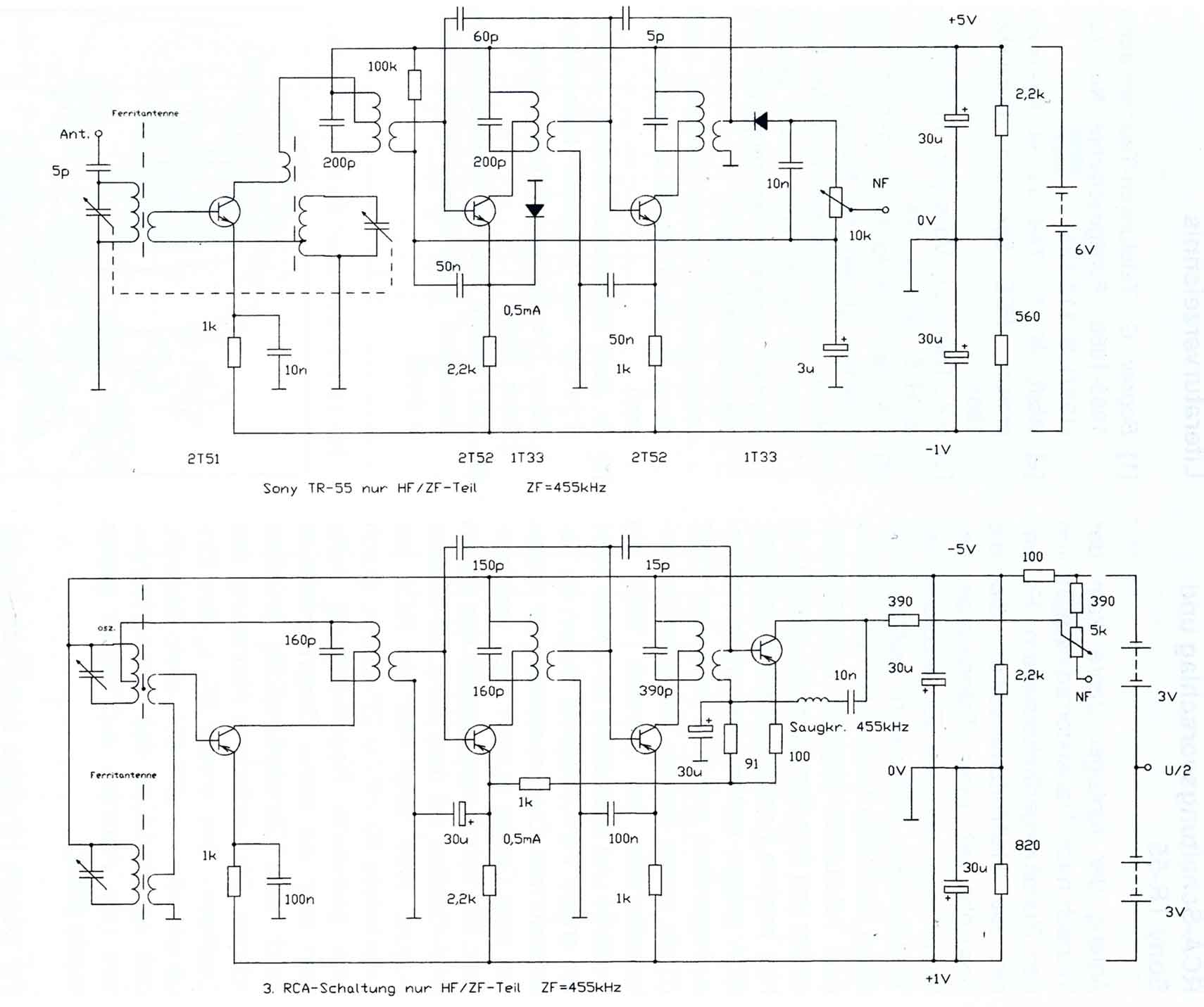
The circuitry of the Regency exhibits several unique characteristics. Notable features include the self-oscillating mixer stage, the base bias voltage of the second IF stage derived from the AF power stage, an unusual IF frequency of 262 kHz, and...

Closing the protective circuit (R1 to R2) applies positive voltage to the gate of SCR1 and activates the alarm. It can only be turned off with SI. The described circuit utilizes a Silicon Controlled Rectifier (SCR) as a key component...
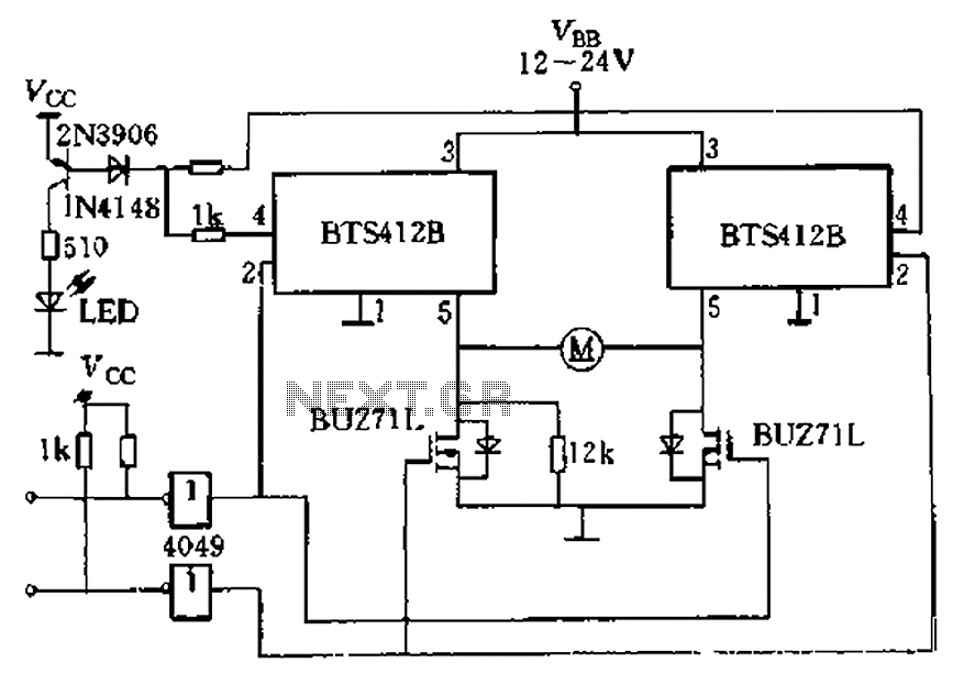
The BTS412B functions as two high-side power MOSFET switches, while two BU271L (50V, Zhang 1n) serve as low-side switches, forming a bi-directional H-bridge DC motor drive circuit. This configuration is designed for electrical automatic door systems, capable of handling...

Electronic FM Telephone Transmitter Schematic. The following schematic design illustrates a circuit diagram for an FM telephone transmitter built on a compact PC board layout. This small design allows it to be easily integrated within the housing of a...

This circuit is a musical doorbell. When the button S1 is pressed, a short melody plays. If the button is pressed multiple times in quick succession or held down, a different melody is generated, and the melody plays for...