lantern dimmer flasher circuit diagram

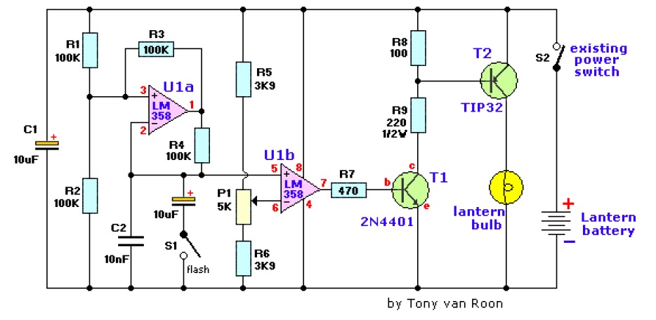
The electronic lantern control circuit enhances an existing battery-powered lantern or flashlight, or can be incorporated into a custom design, by providing high-efficiency dimming and flashing capabilities. This circuit is particularly useful in automotive applications, serving as an effective lamp for changing flat tires, reading in the back seat, or conducting emergency engine work. The flasher mode is beneficial for alerting other drivers to potential issues and can be adjusted for a very short flash duration for extended use, such as when a vehicle needs to be left on the roadside overnight. In camping scenarios, it functions as a low-power night light for tents or portable toilets, allowing users to select the desired level of illumination. The flasher mode is also advantageous for locating boat docks in darkness or attracting fish. Additionally, at home, the flasher provides a means of signaling guests when they have arrived at the correct location or can add flair to battery-powered holiday decorations. The circuit is designed for use with 6 or 12-volt lantern batteries but is compatible with power supplies ranging from 4.5 to 15 volts without requiring any modifications.
The electronic lantern control circuit is comprised of several key components that facilitate its various functions. The core of the circuit typically includes a microcontroller or timer IC that governs the dimming and flashing operations. This microcontroller can be programmed to manage the intensity of the light output, allowing users to adjust the brightness according to their needs.
For the flasher mode, the circuit employs a pulse-width modulation (PWM) technique, which enables rapid on-off cycling of the light source, creating a flashing effect. The duty cycle of this PWM signal can be adjusted to modify the flash duration, making it suitable for different applications, such as emergency signaling or low-power illumination.
Power management is an essential aspect of this circuit, ensuring that it operates efficiently across a range of input voltages. Voltage regulators or DC-DC converters may be integrated to maintain stable operation regardless of the supply voltage, enhancing the circuit's versatility and reliability.
The output stage often consists of a driver circuit that can handle the current requirements of various light sources, including LED arrays or incandescent bulbs. Protection features such as fuses or current-limiting resistors may also be included to safeguard against overcurrent conditions, ensuring longevity and safety during operation.
Overall, this electronic lantern control circuit provides a multifunctional solution for portable lighting needs, combining efficiency, flexibility, and ease of use in a compact design.The electronic lantern control circuit adds high-efficiency dimming and flashing to an existing battery powered lantern orflashlight or to a custom design. For the car it makes a great lamp for changing a flat tire, back seat reading or emergencyengine work.
The flasher mode is useful for warning other drivers of your troubles and it may be adjust ed to have a veryshort flash duration for long-term use as when the car must be left on the shoulder over night. When camping it is great asa low-power night light for the tent or the portable `potty`-you may select only as much light as you need!
The flashermode is useful for finding a boat dock in the dark or even attracting fish. At home, the flasher is a great way to tell guestswhen they have found the right house or to "jazz up" battery powered holiday decorations. The circuit is intended for 6 or12 volt lantern batteries but it should work well with supplies from 4.
5 to 15 volts without any modifications to the circuitas shown above. 🔗 External reference


