
Touch Switch Using Cd4066B Circuit
The described circuit employs a touch-sensitive switch SI that triggers a relay or electronic switch mechanism. Upon activation of SI, the resistor R4 is subjected to a high voltage, which indicates that a sufficient current is flowing through R4. This increase in voltage at the control input enables the latching mechanism to engage, maintaining the switch in an 'on' state even after the initial touch is released.
The inclusion of switch S2 serves as a reset or deactivation feature. When S2 is activated, it pulls the voltage at R4 low, effectively reducing the control voltage to a level where the latching mechanism is disengaged. This action breaks the circuit, returning the switch to its 'off' state.
The circuit's design is beneficial for applications requiring a momentary activation with a persistent output, such as in lighting control systems or automated devices. The use of resistors in conjunction with switches allows for simple yet effective control logic, ensuring that user interaction is intuitive and responsive. Proper selection of resistor values and switch types is critical to achieve the desired sensitivity and operational reliability in the circuit. When touch switch SI is activated, R4 is driven high, and the control voltage goes high, which latches the switch. When S2 is activated, R4 goes low and the control voltage goes low, which deactivates the switch. 🔗 External reference
Related Circuits
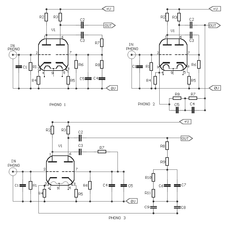
The three circuits were based on the vacuum tube ECC83, designed to produce phono preamplifiers in compliance with RIAA standards. The described circuits utilize the ECC83 vacuum tube, a dual-triode component known for its low noise and high gain characteristics,...
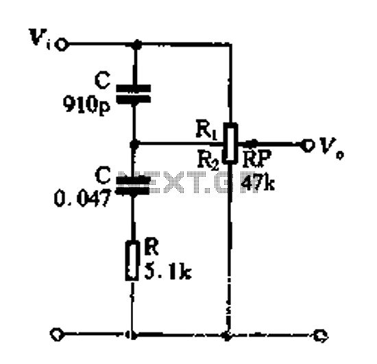
Figure 1-89 illustrates a loudness control circuit. A potentiometer is connected to ground, with 30% of the total resistance at the tap. When the slider arm is adjusted to the tap position, a midrange attenuation of 30 dB is...
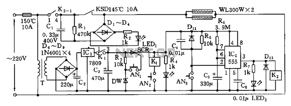
The disinfection cabinet circuit operates on the principle of using infrared heating within a closed cabinet to create a high-temperature environment for disinfecting tableware. The circuit includes an AC buck regulator, an infrared heating circuit, and a timing control...
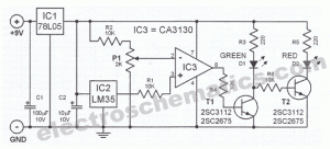
Measuring the temperature of coffee is important because the taste of coffee relies on two main factors: the strength of the coffee and its temperature. Measuring the temperature of coffee can be accomplished using a simple electronic circuit designed to...

A digital stopwatch or digital timer circuit schematic is constructed using the timer IC LM555 and the 4-digit counter IC MM74C926, which is paired with a multiplexed 7-segment LED display. The digital stopwatch circuit utilizes the LM555 timer IC configured...
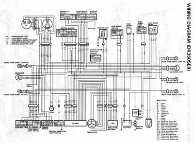
The following circuit illustrates the electrical circuit diagrams for the Toyota Supra. The diagrams indicate the point at which the power source is received. The electrical circuit diagrams for the Toyota Supra provide a comprehensive overview of the vehicle's electrical...
Warning: include(partials/cookie-banner.php): Failed to open stream: Permission denied in /var/www/html/nextgr/view-circuit.php on line 713
Warning: include(): Failed opening 'partials/cookie-banner.php' for inclusion (include_path='.:/usr/share/php') in /var/www/html/nextgr/view-circuit.php on line 713