
Laser Alarm Circuit
The proposed circuit design incorporates a light-dependent resistor (LDR) as the primary sensor, which reacts to changes in light intensity. When the light beam directed at the LDR is interrupted, the circuit triggers a response from a timer circuit integrated with a 4060 binary counter. The timer is configured to keep the alarm active for a predefined duration, which can be adjusted based on user preferences.
The 4060 IC serves multiple functions in this design, including frequency division and timing control. The output from the LDR is processed through an operational amplifier to ensure that the signal is strong enough to trigger the 4060. The timer output can be set to various time intervals, allowing for flexibility in alarm duration.
For enhanced reliability, the circuit can be expanded to include multiple LDRs or other types of sensors, such as passive infrared (PIR) motion detectors. This configuration would require a logical AND gate to ensure that the alarm only activates when all sensors are triggered, reducing the likelihood of false alarms.
The output of the circuit can be connected to various alarm systems, including sirens or notification systems, ensuring that the alert is both audible and visible. Additionally, the design allows for the incorporation of visual indicators, such as LEDs, to provide a visual cue when the alarm is active.
Overall, this schematic provides a foundational approach to designing an effective alarm system that can be customized and expanded to meet specific security needs. The use of simulation software facilitates testing and refinement of the design before physical implementation, ensuring a robust and functional electronic solution.I had a very basic understanding of electronics and how they worked, so when my friend asked me to look at a schematic he found on the net, I jumped at the chance. Now the first thing you should know about this schematic is that it is very unconventional in design.
If you are starting out new, then please don`t follow this poor example of how a sc hematic should be drawn. Now the downside of this simple circuit, if you haven`t already noticed, is that the alarm is only triggered when the light beam on the LDR(photo cell) is broken. For instance if someone is walking by and breaks the beam of light for a split second then the alarm will only sound for a split second.
This is total garbage for any useful purpose. I didn`t exactly fall in love with the above schematic as I had immediately recognized where it failed to provide a real alarm`. One where the alarm would sound until it was turned off or a certain time period had elapsed. So I set out my design criteria 3. Time period for the alarm to sound before a it was shut off. Intruders don`t stay around forever, 30 mins to an 1 hour should be long enough toarousethe neighbors and yet not annoy them for the whole day.
This is my idea(with the help of my friends over at electronicspoint. com forums) of how this type of circuit should be designed to be useful. This schematic was done on NI 11 simulation software and as such things like the binary indicators on the output of the 4060 are there for simulation only(required). Refer to the 4060 datasheet on what to do with any unused outputs. Hope someone finds this circuit useful as it can easily be expanded since it uses logic to drive the alarm.
For instance you could expand the circuit to 2 detection circuits and expand the logic to require that both detection circuits have tripped before the alarm sounds. 🔗 External reference
Related Circuits
This inductance meter serves as an adapter for a digital voltmeter (DVM), enabling the voltmeter to measure the value of inductors. The inductance meter is particularly useful in designing switch mode power supplies, as it often requires hand-winding coils...
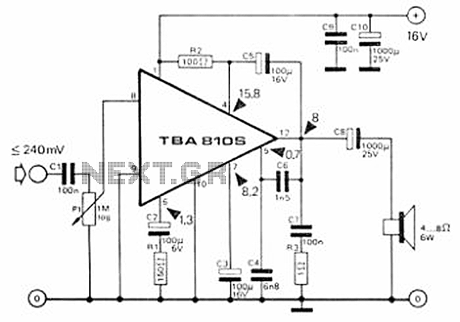
This circuit is a 7 Watt audio amplifier that is simple and easy to construct. It utilizes the TBA810 as the primary component, supported by a few passive components. The amplifier operates effectively, and the necessary kits and components...
Men particularly enjoy the convenience of television remote controls, often to the annoyance of their female partners. They tend to want to know what they are missing when the TV is tuned to a specific program, leading them to...
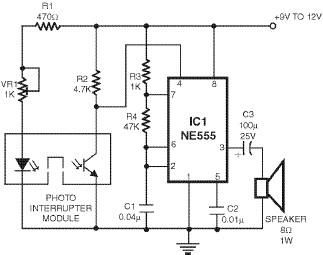
This smoke detector utilizes a 555 timer circuit along with common electronic components. The photo interrupter module serves as the smoke detection element, while the 555 timer is configured in astable mode to function as an audio frequency oscillator,...

The circuit operates from a 5-V supply and has a current consumption of 2 mA. The output functions as a current source that can drive or suppress a current exceeding 75 mA with a voltage swing of 4.5 V....
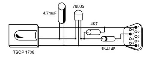
It is unusual that personal computers are not equipped with a standard remote control interface. Many motherboards feature an IRDA port; however, this port is not compatible with the 38 kHz frequencies commonly used by regular remote controls. Fortunately,...
Warning: include(partials/cookie-banner.php): Failed to open stream: Permission denied in /var/www/html/nextgr/view-circuit.php on line 713
Warning: include(): Failed opening 'partials/cookie-banner.php' for inclusion (include_path='.:/usr/share/php') in /var/www/html/nextgr/view-circuit.php on line 713