
Infrared Receiver for PC Schematic andCircuit
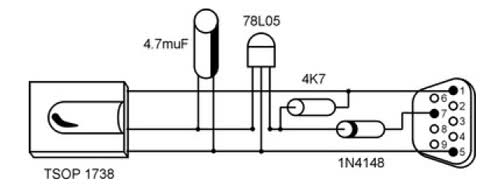
The infrared receiver circuit typically includes a few key components: an infrared receiver module, such as the TSOP4838, which is designed to receive 38 kHz modulated signals. This module is connected to a microcontroller, often a simple Arduino or similar device, which processes the signals received from the remote control. The microcontroller is programmed to interpret the commands sent by the remote, translating them into actions that control various applications on the PC.
Power supply considerations are important; the circuit usually requires a stable voltage source, typically 5V, which can be derived from the USB port of the computer. The output of the infrared receiver module is connected to one of the digital input pins of the microcontroller. The software, often utilizing the WinLIRC library, is responsible for mapping the received signals to specific commands or keystrokes that the PC can recognize.
It is important to ensure that the receiver is positioned correctly and unobstructed to maintain a reliable line of sight with the remote control. Additionally, the range of the receiver can be influenced by the environment, so it may be necessary to test and adjust the placement for optimal performance. Overall, this project provides a practical and cost-effective way to enhance the functionality of a personal computer through remote control capabilities.Actually it`s very strange why PC`s aren`t equipped with a standard remote control interface. A lot of motherboards are equipped with an IRDA port but this isn`t compatible with the frequencies (38 kHz) used in regular remote controls. But WinLIRC comes to the rescue: with just a few components and a little bit of software we can make our own IR-r
eceiver. We will be able to control every application on our pc from a distance up to 30 meters. And to make a receiver you need not be a graduate in electronics. Some basic soldering skills would suffice! Making the receiver: Connect the components as shown in the circuit diagram (Fig 2). If you are not good at soldering get it done from local TV/audio service center. I`ve seen people who have done this for me for Rs. 50. But since I`ve learned a bit of soldering I do it myself nowadays. If you see unrelated pdf files with the description or copyrighted material published, please report to us, we`ll correct/delete it it as soon as possible. NONE OF THOSE MATERIALS ARE HOSTED IN THIS SERVER NOR UPLOADED BY ME IN SOMEONE`S SERVERS. Read our DISCLAIMER for more detail. Information contained herein is provided "as is" without warranty of any kind, either expressed or implied, including any warranty of merchantability or fitness for a particular purpose.
In no event shall ANYONE be held liable for any loss of profit, special, incidental, consequential, or other similar claims. 🔗 External reference
Related Circuits
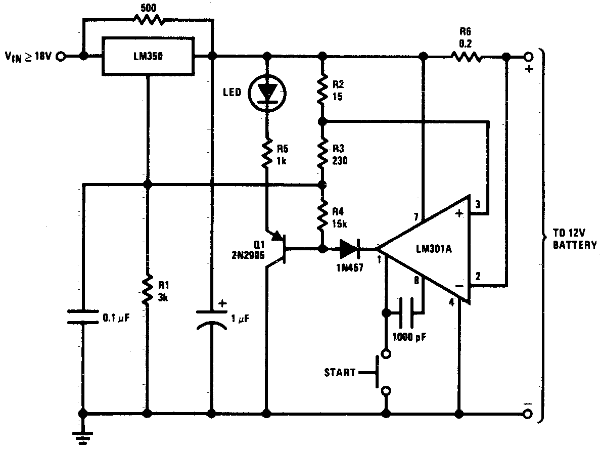
DC 12V Battery Charger Circuit Diagram. This circuit is a high-performance charger for gelled electrolyte lead-acid batteries. The DC 12V battery charger circuit is designed to efficiently charge gelled electrolyte lead-acid batteries, which are commonly used in various applications due...
L1 and L2 were constructed by wrapping three tight loops side by side around a Sharpie marker. L2 was additionally created by wrapping approximately 8 inches of 35 AWG magnet wire around a ferrite core, ensuring that the windings...
The circuit operates at a voltage of 9V with a current consumption of only 5mA. It allows for frequency adjustment within the range of 150 to 180 kHz, featuring a bandwidth of approximately 20 kHz. This configuration ensures that...
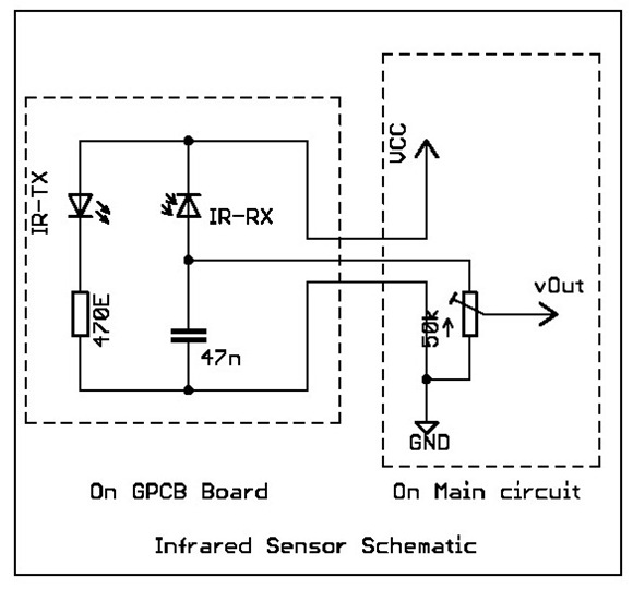
Overview: This tutorial demonstrates the creation of a simple infrared sensor module designed to detect reflecting surfaces. This sensor is capable of identifying reflective materials such as silver or white strips, as well as serving applications in obstacle detection...
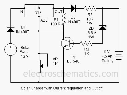
This is a solar charger circuit designed to charge Lead Acid or Ni-Cd batteries utilizing solar energy. The circuit captures solar energy to charge a 6-volt, 4.5 Ah rechargeable battery for various applications. It includes voltage and current regulation,...
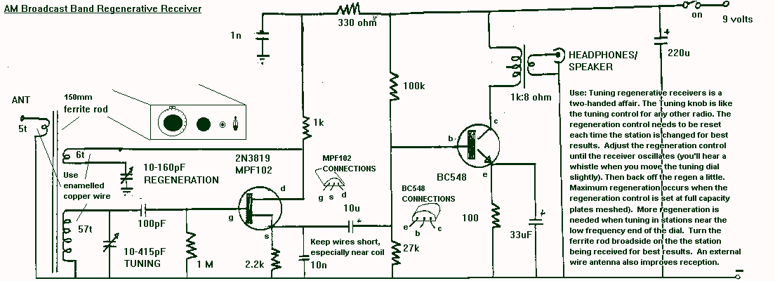
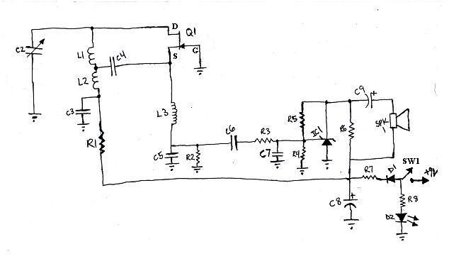
The regenerative detector uses a field effect transistor (FET). Like with the better valve designs, feedback is controlled by a variable capacitor. A ferrite rod was used to allow reception of local stations without an external antenna. This FET...