
Laser beam Sensor
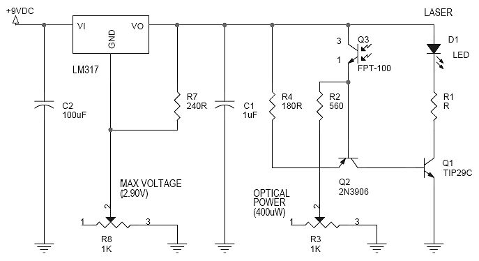
The described detector circuit operates by utilizing a combination of a relay, a light source, and capacitors to create a time-sensitive response to the interruption of a light beam. The core component of this circuit is the capacitor C1, which charges when the beam is broken, activating a connected LED and powering the circuit. The transistor in the circuit remains in the 'on' state while C1 is charging. Once C1 reaches a certain voltage, the CdS (cadmium sulfide) cell can deactivate transistor Q1, which subsequently allows C1 to discharge through resistor R5, thereby resetting the circuit.
The time period for which the relay remains activated is adjustable through potentiometers R1, R2, and R3. R2 can be used to decrease the charging time of C1, effectively shortening the activation duration of the relay. Alternatively, adjusting the value of C1 will influence the duration, with a larger capacitance resulting in a longer time period. A 470µF capacitor is suggested for maximum durations, although the actual time will fluctuate based on the characteristics of the transistor used.
R3 serves to extend the time period by controlling the rate at which C1 charges. An increase in R3's resistance will extend the activation time to a maximum point before it begins to shorten, which is contingent on the specific transistor's properties. A typical value of 100k ohms is recommended for compatibility with most transistors.
The circuit's sensitivity to brief interruptions in the light beam can be improved by enhancing the light source or using larger lenses. The described configuration achieved a range of approximately 25 feet with a "super bright" LED paired with a 1-inch lens in the transmitter and a 3-inch lens in the receiver.
For the transmitter, a simple light source, such as a pen light bulb or a "super bright" LED, is positioned behind a plastic lens. A homemade tube, constructed from poster board or stiff paper, serves to focus the light beam. The interior of the tube should be painted flat black to minimize light scattering. The lens is mounted securely in the tube, and adjustments can be made to the position of the light source within a sliding cylinder to achieve optimal focus on a detection screen.
Potential enhancements to this circuit include the use of modulated signals to minimize interference from ambient light sources and the implementation of infrared LEDs and phototransistors to create an invisible detection beam.a more complex detector circuit which turns the relay on for an adjustable period of time. When the beam is broken, the LED goes on, your effect is powered, and capacitor C1 begins charging. As C1 is charging, the transistor will be kept on. Once C1 is charged, the CdS cell will be able to turn Q1 off again. Then C1 will be discharged through R5 by the relay. Opening switch S1 will disable the time period to allow you to adjust R1. Adjust the time period with R2 (Radio Shack #271-211 $1.50) which shortens the time period by charging C1 faster, or leave out R2 and simply change the size of C1. A 470uF capacitor (Radio Shack #272-1018 $1) can give up to 60 seconds, but that will vary depending on the transistor.
The time period is sensitive to the adjustment of R1, so adjust R1 before adjusting the time period. R3 extends the time period by slowing the charging of C1. The time period can be maximized by adjusting R3. As R3's resistance goes up, the time period will lengthen to a maximum, and then shorten to zero. The maximum depends on the characteristics of the transistor. 100k ohms should work well with most transistors. If the detector misses brief beam breaks, then it's probably on the edge of its range. Larger lenses and/or a brighter light will increase the range. I achieved a range of 25 ft with a "super bright" LED and a 1" lens in the transmitter, and a 3" lens in the receiver. Possible enhancements: Send a modulated signal from the transmitter and detect only that signal to prevent interference from other light sources.
Use an infrared LED and photo transistor pair to make the beam invisible. The transmitter is simply a light behind a 1 to 3 inch diameter cheap plastic lens. I used a toy magnifying glass. See figure 1. Make a tube the size of your lens out of rolled up poster board or stiff paper. Cut one end at an angle to form a hood which will conceal the light from view. Paint the inside flat black. Glue the lens in the tube. Build a cylinder which will slide inside the tube by cutting out two circles of corrugated cardboard and gluing them into the ends of another tube. Mount your light in the center of one end of the slider, and run the wires out the other end. A pen light bulb (Radio Shack #272-1141 $1.19) or "super bright" LED (Radio Shack #276-087A $2.50) is sufficient.
To focus the transmitter, put a white screen of some sort where the detector will be. Adjust the slider to get the brightest spot possible on the screen. Depending on your lens and the distance, the spot may be large. That's okay. Experiment with your lens beforehand and be sure to build the tube long enough to allow the beam to be focused. 🔗 External reference
Related Circuits
This document outlines the transformation of a basic, cost-effective green laser pointer into a laboratory-grade laser. The core of this diode-pumped solid-state (DPSS) laser is an affordable green laser pointer. These pointers are essentially DPSS lasers that include a...

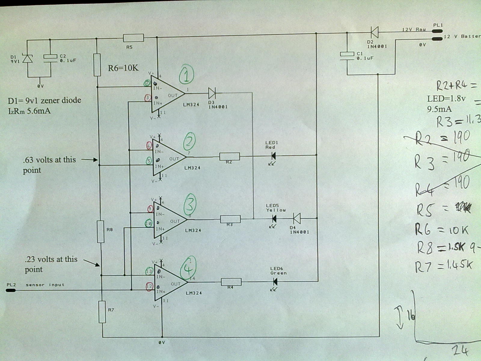
The circuit is designed to sense ambient light levels and activate lights when it is dark. A prototype was successfully built on a breadboard using an LM324 comparator, various resistors, a trimmer resistor, and a photocell. Subsequently, a PCB...
Ions are defined as electrically charged atoms. Positively charged ions have a deficiency of electrons, and negatively charged ions have a surplus of electrons. An ion can also be classified as an atom or molecule with an electrostatic charge....
A 12V power supply is connected to the positive terminal, allowing current to flow through a protection diode and a capacitor that smooths the voltage. A zener resistor (R5) limits the current to the zener diode, which regulates the...

The following circuit illustrates a Robotics IR Navigation Sensor Circuit Diagram. Features include one chip, the 74HC04, and the IR sensor is designed to operate in direct sunlight. The Robotics IR Navigation Sensor Circuit utilizes an inverter IC, specifically the...
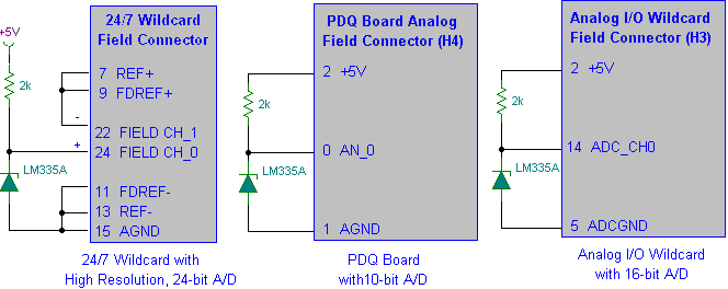
Interfacing the LM335A temperature sensor with A/D converters involves measuring temperature using the LM35 and LM335A sensors alongside the 9S12 HCS12 microcontroller. This process includes analyzing both calibrated and uncalibrated temperature errors of integrated circuit temperature sensors. The LM335A is...